Summary
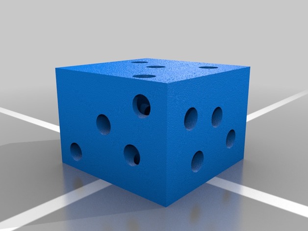
Puzzle Cube
Author: Thingiverse
-
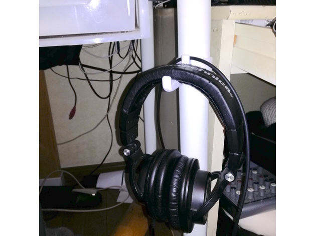
Headphone hook for 40mm pipe 3D Print Model
Summary
I use this by attaching it to IKEA’s ADILS.https://www.ikea.com/jp/ja/catalog/products/00353742/
This requires M3, 10 mm screws and nuts.
Print Settings
Printer:
Snapmaker
Rafts:
Yes
Supports:
Yes
Resolution:
0.15mm
Infill:
8% -
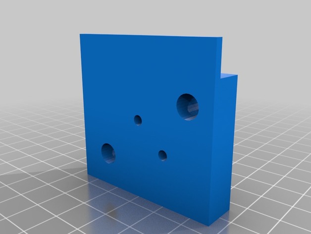
35nmm to 9mm film splitter 3D Print Model
Summary
I make this to cut 35mm film into 9mm film for my old spy cameras. -
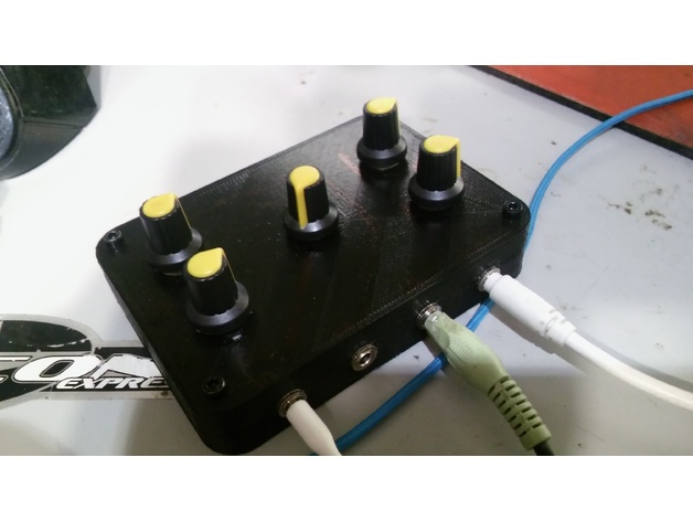
Mini Passive Mixer 3D Print Model
Summary
Plans and more details here : http://therandomlab.blogspot.com/2015/05/simple-passive-monostereo-to-stereo.html
This one does not match the schematic exactly. It has two stereo channels and one mono channel into one stereo out. Used 10K potentiometer, 1K resistors, and 1uF Capacitors. -
Terminator Pop Buddha 3D Print Model
Summary
Didn’t see a Terminator Pop Buddha statue. I combined Geoffro’s T-800 head and Buddha statue.
I though meditating on a pile of human skulls was more appropriate than the original base.
I used multiple skull models for the pile.
I don’t have a 3d printer yet, so I would appreciate any feedback from people who give it a shot. I’ve cleared any problems Meshmixer and loaded it up into Cura to look at the layers for anything obvious.
These skull base uses the following models:
Female skull injured by sword
Provinciaal depot voor archeologie Noord-Hollandhttps://sketchfab.com/models/be61ad2567024febbc1b9cc566a1d372#
Cranium
UNCG Imaging Labhttps://sketchfab.com/models/c39855833ff74943a2847972c9ff8700
kobanian skull (800 BC)
kantemratihttps://sketchfab.com/models/1d32fa630aeb46988f75c397df3cc429
There are a few more skulls I still need to add attributions for. -
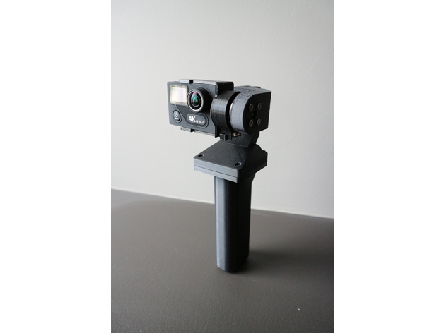
YAPM Handheld Brushless Gimbal 3D Print Model
Summary
Yet Another Poor Man’s Handheld Brushless Gimbal
Ever since I got the Mavic pro i haven’t been using my home built drones for aerial photography anymore. So I figure I’ll turn my cheap chinese 2 axis brushless gimbal into a handheld one so i can use it when i go traveling.
I’ve looked at the other designs on thingiverse but i didn’t like that they all left wires hanging about in the open. No offence to the other designers… I wanted one that would look much cleaner and travel better without having to worry about wires snagging on stuff. So I set out to design my own.
I designed this to be used with an EKEN H8 Plus and action cam with the same body format as Gopro Hero 3.
This design makes use of contact adhesive to glue the parts together and requires soldering and basic electronics skills. Some filing and fitting of the parts may be required. Do not attempt if you have a problem with any of the above.
Print Settings
Printer Brand:
Prusa
Printer:
i3 MK3
Rafts:
No
Supports:
Yes
Resolution:
.20
Notes:
Infill doesn’t matter as most of the parts are “thin wall” so most slicers would automatically do 100% fill anyways.
I printed this in PLA and the parts fit quite nicely. Where it’s too tight i used a file or sand paper to open it up a little. if printing in ABS it will shrink and make it too tight for the motors to move freely, so scale it up appropriately. I haven’t printed this in ABS so i can’t say how much to scale up.
Post-Printing
0. Required parts
Printed parts
No name chinese 2 axis gimbal like this one https://goo.gl/GvutmB
Mini rocker switch like this one https://goo.gl/tPpHTY
RC radio battery like this one https://goo.gl/znMdYC
JST connectors like these https://goo.gl/r9qnca
4 M3 x 14mm bolts and nuts, i recommend just getting a box of assorted ones like these https://goo.gl/eiZ4qW
Heat shrink tubing to fit over the legs on the power switch
Contact adhesive to glue PLA parts together
1. Disassemble the aluminium gimbal
Disassemble the aluminium 2 axis gimbal.
Remove all the header pins and the JST power connector on the control board.
I chose to eliminate header pins to make it more compact, the motor wires will need to be direct soldered to the pads during assembly. Make note of which wire connects where if necessary.
2. Remove support material
Remove support material from the parts. The support material inside the wire ways is a pain to remove; some spit grit and good ol’ elbow grease may be needed here.
It may be possible to print the motor arms without supports, but that will depend on your particular printer’s abilities with overhangs. i opted to go through the work of removing support just to make sure everything comes out right.
Take this time to ream out all the bolt holes with a drill bit.
3. Glue parts together
Apply contact adhesive to flat flared part of the part named “handle” and glue it to the flat side of the part named “bottom case”. Try to get the back edge to line up and left right centered on the bottom case. I measured the distance on each side and marked the position by scoring with an exacto blade to help me position the handle.
Take the part named “top case” and the part named “roll motor”. Use a file and an exacto blade to get the mating surfaces free of residual support material and as flat as possible. Apply contact adhesive to the indent in the top case around the opening and glue the “roll motor” part to the top case.
Take the parts collectively named “camera mount” and glue the two larger parts together. refer to the pictures to see how it’s supposed to go together.
The little “M” shaped clip is to hold the IMU sensor in place and will be needed during assembly.
Set aside and allow adhesive to cure.
4. Mounting the motors
Take the IMU sensor liberated from the aluminium gimbal and disconnect the cable on both ends. Feed the cable through the wireway in the part named “pitch motor”.
Take one of the brushless motor that was liberated from your aluminium gimbal, feed the motor wires through the part named “pitch motor” from the opening with the 4 hole bolt pattern and mount the motor with the 4 M3 screws that came with the original gimbal. You may choose to use other bolts, but be careful not to choose ones that are too long as it will damage the motor windings.
The parts was designed such that where the wires comes out of the motor points directly down the wireway. There is a gap between the motor and the edge of the opening on the inside face of the arm to accommodate free movement of the IMU sensor cable.
Now take the “pitch motor” assembly and feed the motor and IMU sensor wire through the gap between where the other motor goes on the “roll motor” part and then down the wireway and through the opening in the top case.
Take the other brushless motor and feed the motor wire down through the wireway the same as the other wires and mount the motor onto the part named “roll motor”. Also mount the pitch motor assembly to the roll motor.
Rotate the assembly throughout its range to ensure there is enough free play such that the wires are not strained from the movement. I used tweezers to reach in and pull some wire back into the wireways so that there’s some slack to allow for free movement.
5. Wiring it up
At this time the control board should be relieved of its header pins and power connector.
Solder a JST female connector to the mini rocker switch in series on the negative (black) side of the wire. Put some heat shrink tubing over the legs on the switch to give it some protection. Now feed the wires coming from the switch through the switch opening on the handle and snap the switch into place. bring the wires to be soldered onto the control board up through the bottom case opening and solder them to the control board.
Observe correct polarity as there is no diode protection on these boards. A mistake here could let out the magic smoke and render the board defunct.
Now take the top case/roll motor/pitch motor assembly. There should be 3 sets of wires dangling down from the top case wireway opening as follows
IMU sensor cable
Roll motor wires
Pitch motor wires
Cut the connectors off the motor wires, strip the wires and solder onto the corresponding solder pads on the control board as noted in step one during disassembly.
6. Affix the IMU sensor, camera mount
Place the IMU sensor into the slot on the camera mount and install the “M” shaped clip. The IMU sensor should be affixed into place. Run the IMU sensor cable along the space around the motor and connect to the IMU sensor. Mount the camera mount onto the pitch motor with the 3 screws that came with the original gimbal.
Rotate the camera mount assembly 180 degrees and ensure there is enough slack in the IMU sensor cable to allow for free movement.
Connect the other end of the IMU sensor cable to the control board.
7. Apply power and test
As i didn’t design an opening to allow for USB connection for PID tuning, at this point i recommend connecting the battery and testing before final assembly.
Just like tuning the gimbal on a drone, the action cam should be installed in the camera mount for weight balance.
8. Case closed
Use 4 M3 x 14mm bolts and nuts to assemble the top case and bottom case assembly together with the control board in between. The top case was designed with enough space to hide all the wires inside without pinching them, but do be careful not to pinch any in between the bolt posts.
Now the gimbal should be ready for action. Connect the battery and shove it up the handle, shove the extra wires and connects from the battery in the free space around the battery. Snap in the pommel cap. The positioning tabs on the cap may need to be filed down a bit for an easier fit.
Enjoy. -
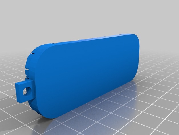
Keychain 3D Print Model
Summary
customizable keychainStandards
NGSS
Overview and Background
Lesson Plan and Activity
no lesson plan
Materials Needed
3d printer -
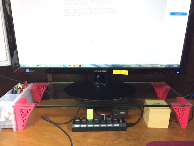
Monitor Stand 3D Print Model
Summary
You can print the center leg to support the monitor stand in case it is long.
Print Settings
Printer Brand:
Prusa
Printer:
i3 MK3
Rafts:
Doesn’t Matter
Supports:
No
Resolution:
0.15
Infill:
20 -
Discone Antenna Hub 400MHz and up, 70cms, ADS-B 3D Print Model
Summary
The Discone antenna is remarkable in that it is capable of receiving and transmitting over a wide range of frequencies with good matching. Because of this, it is a good match for SDR receivers such as the popular RTL-SDR sticks.
The only really tricking thing about making a discone is that the disc has to be balanced at the very top of the cone, which is mechanically awkward.
The two parts here allow the cone to be solidly clamped and provide an adequate base for the disk. There also two holes for bring the coax centre and braid out to the disc and cone.
The base part has a socket at the bottom for 25mm (1 inch) plastic conduit for mounting
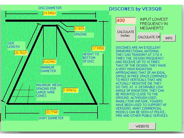
This antenna illustrated is designed for 400MHz and up, and as such transmits well on the 70cms amateur band, US and UK PMR channels and 23cms. It also receives aircraft ADS-B signals very well. I used .3mm plastic sheet for the cone and 2mm plastic for the disc, and then covered them with aluminium weatherproof tape. Be sure to check for continuity across the tape stripes.
The screenshot is of a calculator by VE3SQB which can be downloaded from http://www.ve3sqb.com/ if you want to make attenna’s for other ranges. -
CR-10S Hinged Filament Sensor Mount (Bottom Plug) 3D Print Model
Summary
CR-10S Hinged Filament Sensor Mount (Front Plug)https://www.thingiverse.com/thing:2791872
CR-10S Hinged Filament Sensor Mount (Bottom Plug)https://www.thingiverse.com/thing:2826099
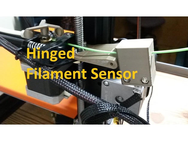
Lets be honest. The filament runout sensor is a great addition to the Creality CR-10S, but the factory slide-on mount that Creality supplies sucks. I download and printed several other designs from here and just wasn’t happy with the alignment or functionally of them, so I designed my own.
I wanted the filament to be feed straight thru with enough room inbetween to manage any kinks or wobbles in the filament with your hands. I also wanted a better way to reduce friction thru it when near Z=0 and Z = 200+ as the filament is drug thru the horizontal position of the sensor first which is dependent on the way you install the roll (over the top or under). Thats when putting a hinge inbetween seemed like the perfect solution as I run a TUSH spool holder with the extruder feed off the bottom of the spool. I designed this Hinged Filament Sensor Mount so it can be bolted onto the Z-axis brass lead screw nut using factory hardware, then the mount is stabilized to the Z column roller mount right at the hinge. I also designed it so you could run the sensor fully enclosed or with the printed cap to keep crud out. You will need (2) M3X20 screws with (2) M3 hex nuts. Hinge is printed in place.
Please note that after printing you will need to carefully twist the built-in support material off in the same direction as the pivoting hinge. If you use flush cutter on the support material, you may end up splitting the mount in half. The hinge for this design requires a M3 x 30mm LG screw and a M3 Nut as I couldn’t model it assemblied without alot of wasted support material.
The sensor I designed this around can be purchased here:https://macewen3d.com/products/cr-10-cr-10-s4-and-s5-replacement-endstop-limit-switch
Which is the same as the factory Creality CR-10S filament runout sensor or Axis stop sensors. My machine actually came with a spare, which made designing/refining it pretty easy.
Some people didn’t like my previous version of this mount since the plug for the sensor was in front, so I remixed it so the plug is now facing downward. -

Golf Ball Belt Clip Remix 3D Print Model
Summary
This is a remix from the TheKre8Group’s one.
Added 3 tee holders, and a slot to label/mark the balls (putting helper).
Printing tips:
o.2 layer height
perimeter width : 0.45
and allow single extrusion wall for the outer perimeters (that’s for the support wall).
All attribution to TheKre8Group! -
Triangular Sinusoidal Vase 3D Print Model
Summary
I’ve got a little overhang on one face but it is still a nice print ! -
3D Printed Bridge 3D Print Model
Summary
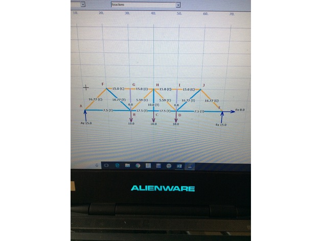
This is a 3D printed bridge that can support over 100 times its own weight. The members in the still file section above this description are printed as follows: Members 1 and 3=100% infill, members 2 and 4=30% infill. The load to weight ratio of this bridge is a whopping 137! The members can be slightly fragile at the points of connections, and for this reason the individual stl filedps for each member are included for piece by piece printing. -
Wallmounted S8 Wireless Charger 3D Print Model
Summary
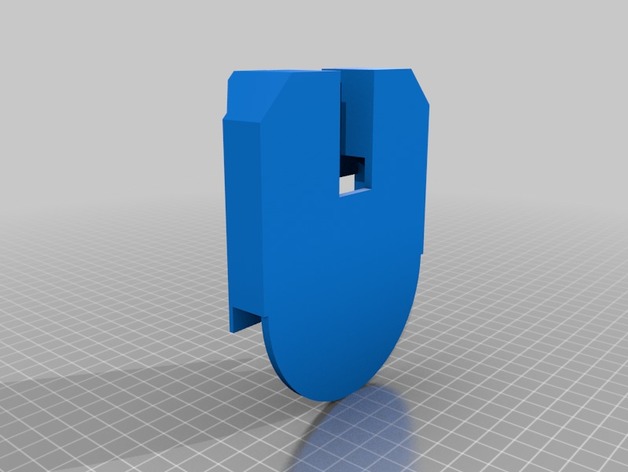
Holds naked S8 and a 95mm dia/10mm thick wireless fast charger. Use VHB tape along edge of wireless charger to fix to the mount and use 3M strips to fix to wall. -
Veronica’s Heart 3D Print Model
Summary
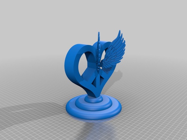
Ever since my daughter was little she loved drawing peace signs and hearts with wings. She really wanted me to print her a peace sign and we really couldn’t find one we liked so I made this.
Print Settings
Printer Brand:
Creality
Printer:
CR-10
Rafts:
Doesn’t Matter
Supports:
Yes
Resolution:
.2
Infill:
15How I Designed This
-
Wheel tank 3D Print Model
Summary
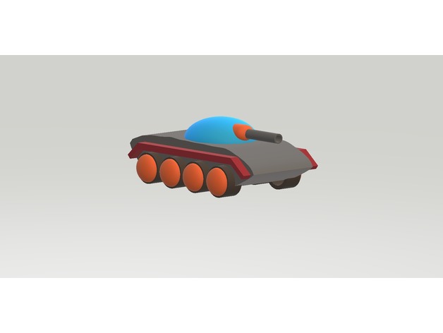
This a kind of 8 wheels Tank.
I think a good tank require: Speed, armor, and fire power.
Transport capacity must also be available.Overview and Background
Introduction
I design this by Paint 3D, 3D builder.
I build tank scale model for fun.
I have some idea to improve a tank, and try make it more reasonable and Universal. -
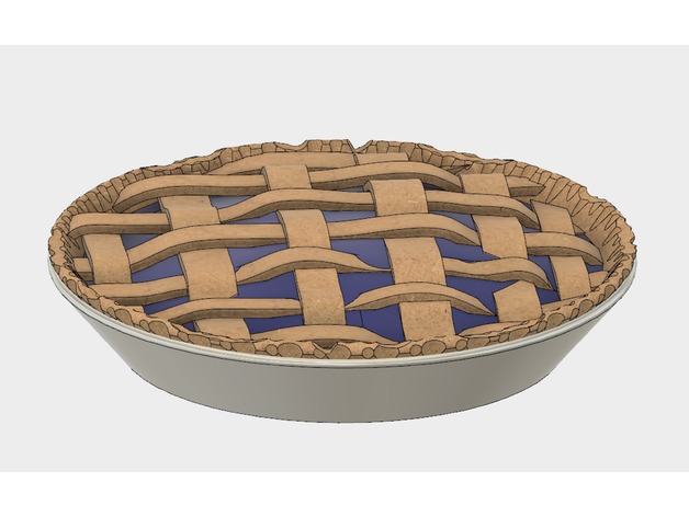
Pie 3D Print Model
Summary
Pie designed for either a single color printer (Whole Pie.stl) or for multi-color printers with the other parts. This is a work in progress, and will likely receive some tweaks.
You will likely need to print it at a reduced size – the actual file is 254mm in diameter. -
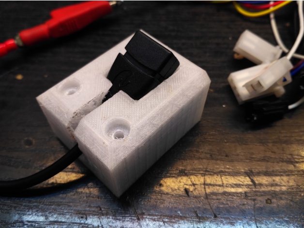
holder for little usb adapter 3D Print Model
Summary
This is a holder for small 10cm usb adapter from ebay. -

TRX4 BODY MOUNT FOR JEEP RUBICON 3D Print Model
Summary
This is the body mount for the Jeep Rubicon www.thingiverse.com/thing:2605921, for TRX4 chassis. Body needs drilling aligning to the holes of the mount.
Post-Printing
Remove screwsDetach the step board
Replace it with the printed body mount
-

Removable Extruder Fan Holder A8 with Z probe 3D Print Model
Summary
This design allows you to easily replace your filament by manually removing the extruder fan.
The extruder fan sits on on sliding slot, and to remove it you just need to pull it up.
I have add a Z-Probe ring if you have a sensor..
This is a remix from petiz ( https://www.thingiverse.com/thing:2822215 )
What you need to know:
print the design
remove the heatsink and fan cover
use the same two 50mm screws to put the mount in place
add the Z-Probe
simply slide the fan in!
Feel free for comments and photo if you make it
Print Settings
Printer:
Anet A8
Rafts:
Doesn’t Matter
Supports:
No
Infill:
15% – 20% -
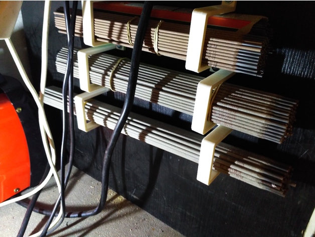
holder/organizer for welding electroder of something else 3D Print Model
Summary
This is my “vision” for organizing welding electrodes in workshop.
I’ve made this in different scales. -
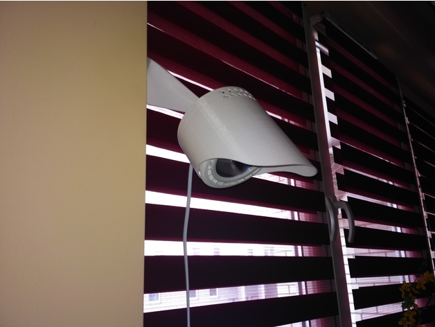
Lamp/holder for led bulb GU10 with adjustment 3D Print Model
Summary
This is holder for GU10 led bulb with diameter 110mm. This have ball type adjustment. -
Kitty LItter Locker bag slitter 3D Print Model
Summary
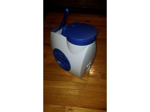
This piece can replace the original bag slitter on a litter locker(see photo of white and blue litter locker). This is a device is used to store dirty scoopable cat litter and contain it in a sealed bag for disposal. Eventually the original slitter becomes dull and this allows you to replace the old slitter and insert a new razor blade for cutting the bags.
Post-Printing
setup with a standard straight edge razor blade
You will notice a 2.5 mm wide slot in the edge of the unit which should be just wide enough to slip a straight edge razor blade in to expose the sharp edge of the blade. Use the slim flat piece as a shim to lock the blade into place. You can cut off the excess, but leave enough so that you can easily pull it out and replace the razor if it ever gets dull again.
How I Designed This
Litter locker removal of old slitter
Eventually the razor in the old slitter slot will become dull or bent and it will not easily cut the bag ends any more. The original slitter is removable, but you cannot replace the blade. This print will allow you to replace the blade and slip it into the same slot as the old one.
The OEM slitter is located just behind the back side of the input schutte. it can be removed by using two flat screw drivers to carefully lift the white retainer enough for the hold down notch to go into the locker, then just push out the old one. (the photo showing the original slitter with the rounded edges. Once the old one is removed you can insert your replacement and once again the bags will melt when you pull the end of the back into the slit. -
Delta 5 – with voltage regulator and heat sink 3D Print Model
Summary
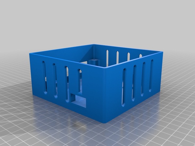
Just trying to add a voltage regulator, and some heat sinks I bought 😀 -
Temperature display mount for Anycubic 4Max 3D Print Model
Summary
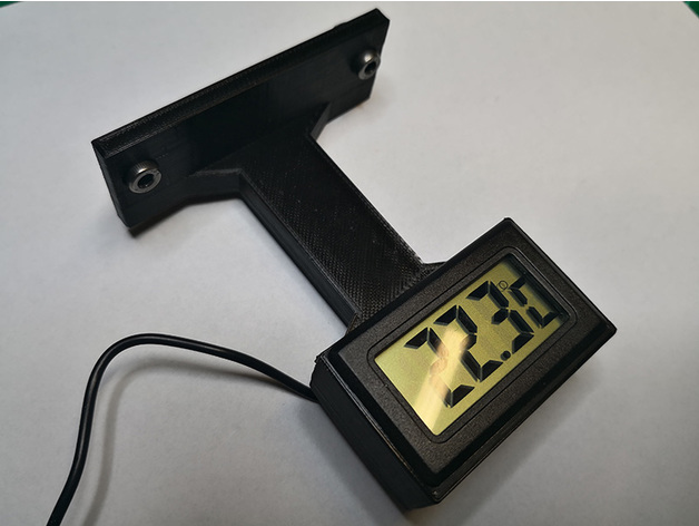
Simple temperature display mount for Anycubic 4Max, it is mountable on the aluminum profiles, up or down side behind the Plexiglas door, there is enough room in the enclosure for the senor wire to mount the display upside down.
If you are lucky enough like me you might have spate T-Nut bolts from the kit otherwise just search for 4mm T-Nut bolts.
Credit: I got the housing from user selmo here: https://www.thingiverse.com/thing:761721 modified the inner part and holes for easy printing.
The sensor I used is at least 10 years old, but you can still buy it here:https://www.aliexpress.com/item/LCD-Digital-Tank-Water-Meter-Detector-Thermometer-Electronic-Fish-Tank-Water-For-Aquarium-Drop-Shipping-Support/32799423978.html
Print as you wish, no supports needed. -
RPG Status Token Charmed 3D Print Model
Summary
charmed / in love / healing / etc
these are meant to be used for multiple purposes / games
Print Settings
Printer Brand:
SeeMeCNC
Printer:
Rostock MAX v2
Rafts:
No
Supports:
No
Resolution:
0.2mm
Infill:
100% -
Support iPad for DJI Mavic Pro Remote Control 3D Print Model
Summary
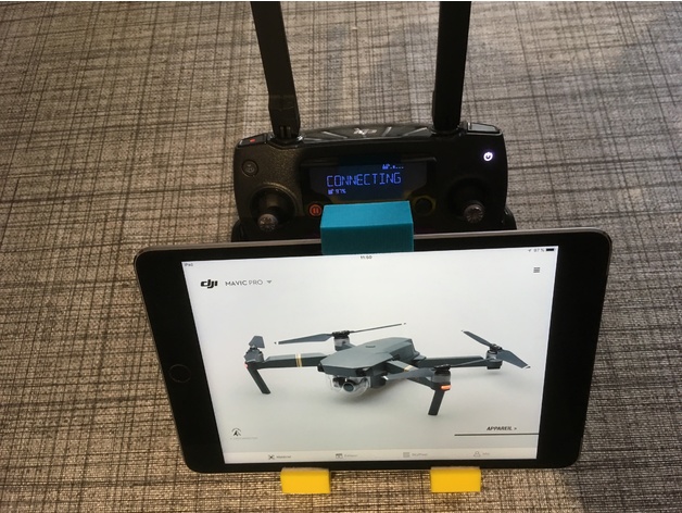
Support Apple iPad Mini 2/3/4 for DJI Mavic Pro Remote Control .
You need a M6 bolt, very careful when tightening the screw
not to break the bracket !
And you need a Self Adhesive Sticky for ipad protection !
Enjoy
Print Settings
Printer:
CTC I3 PRO B CLONE PRUSA
Rafts:
Yes
Supports:
Yes
Infill:
50% -

Altoids Tin Staunton Chess Pieces 3D Print Model
Summary
These are the pieces for my Altoids Tin Chess Board at: https://www.thingiverse.com/thing:2823112
They are meant to accept 4 mm X 2 mm disk magnets. You can find these cheaply from China on eBay in quantities of 500 for less than $10. I was trying to figure out how to make a magnetic chess set without using a stupid amount of magnets. It occurred to me that a flat steel sheet would work, but I had none. These tins on the other hand, I have tons of. They only cost a few dollars anyway and come with mints.
The pieces fit upright with the lid closed just fine. They measure about 7 mm diameter at the base of each piece.
Print Settings
Printer:
Dildahmetron
Rafts:
No
Supports:
No
Resolution:
0.4 mm nozzle w/ 0.2 mm layer heights
Infill:
15% but they’ll probably be solid anyway
Notes:
Be careful removing them from the bed. -
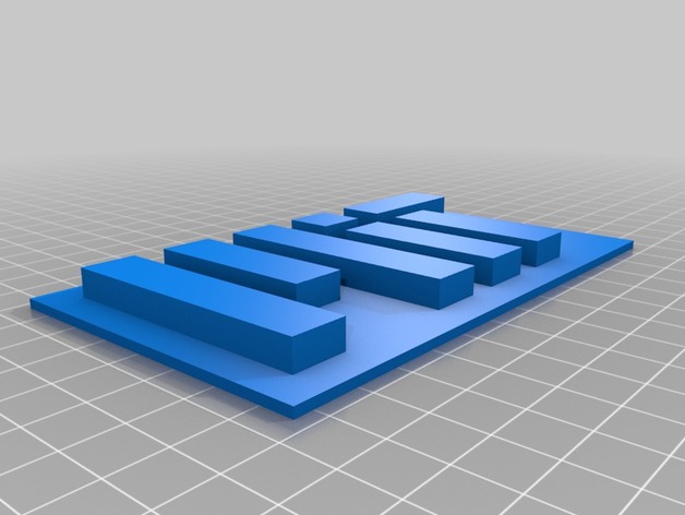
MIT Logo 3D Print Model
Summary
Here is a 3D Model of Massachusetts Institute of Technology’s (MIT) logo. Hope you enjoy!
Print Settings
Printer:
Anet a8
Rafts:
No
Supports:
No
Resolution:
.1-.2 -
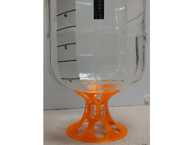
Carboy Dryer 3D Print Model
Summary
This is a stand for drying a glass carboy after washing it. Fits both of my 5gal and 6.5gal glass carboys. The neck of the carboy is held in place so that it cannot tip while in the stand.
The design is made using two bezier curves, extruded rotationally, and then rounded holes punched in the sidewall for airflow and less material usage.
The scad file is attached, which allows easy editing of diameters, heights, angle of carboy glass where stand supports it, number of “legs”, ratio of legs to holes, etc. Note that at full resolution, it takes ~10 minutes to perform a final render the object.
Print Settings
Printer Brand:
Wanhao
Printer:
Wanhao Duplicator i3 Plus
Rafts:
No
Supports:
No
Resolution:
0.2mm
Infill:
40% cubic subdivision
Notes:
No supports should be required. I printed in PETG for water resistance. -
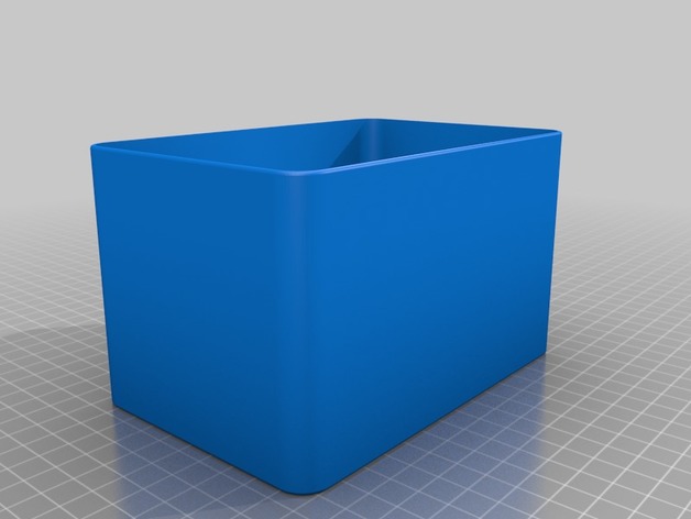
Can of Worms 3D Print Model
Summary
This is literary a can of worms (ok, maggots or larvae really). We needed a suitable container to store food for our bearded dragons and the ones we had was either too big or too small. This one is just perfect. I initially made the walls thinner (1.2 mm == 3 layers) but the walls kept bulging so I had to increase the thickness to 1.6 mm which equals 4 layers with a 0.4 mm nozzle. What Simplify3D does is to make an inner and an outer layer and then fill the middle with a zigzag pattern. This seems prevent the walls from bulging when I print with PETG. The lid has vents on top as well on the sides, so storing one CoW on top of another should work without hampering ventilation. -
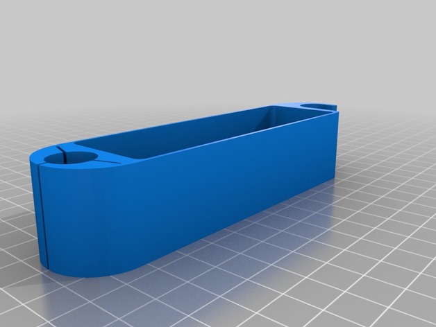
1/4 inch bit holder (multi-tool) 3D Print Model
Summary
1/4 inch bit holder for modular multi-tool. Holds up to 36 bits (less with snap for .375 OD bit driver).
You’ll need (2) 1/4-20 x 1.5″ screws and (2) nuts.
I designed the bit holder and tool snap. Multi-tool designed by Gregg Meyer
Print Settings
Printer:
Monoprice Maker Select Mini v1
Rafts:
Yes
Supports:
No
Resolution:
0.1mm – 0.3mm
Infill:
Doesn’t Matter
Notes:
to make bit holder print:
(2) standoff
(2) side
(1) holder_36
for bit driver holder:
(1) driver_snap
(1) driver_snap gripper
driver snap gripper is glued to driver snap. I used superglue.
substitute (1) “side” for (1) “side for carriage bolt” if you want to use carriage bolts. Some files will need to be rotated before printing. I tweaked dimensions to make things fit because I can’t be bothered to dial in my inexpensive printer. Hopefully everything fits for you! -
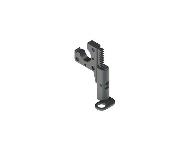
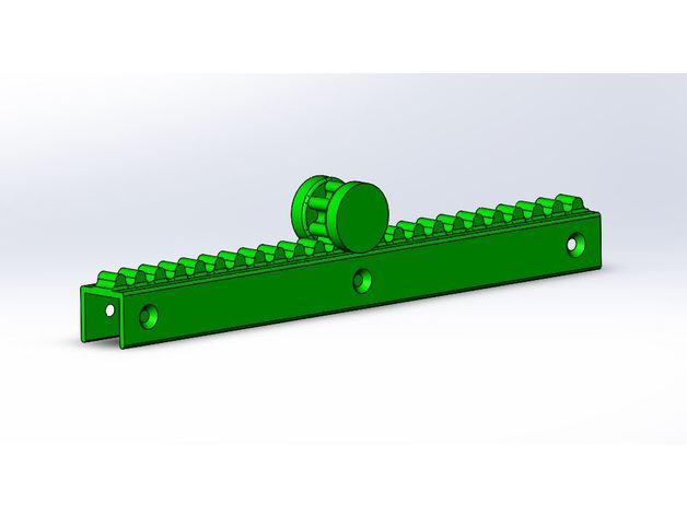
INDUCTIVE SENSOR RACK AND PINION – DRAKON EXTRUDER BODY 3D Print Model
Summary
THIS IS A MANUAL ADJUST SENSOR CARRIAGE FOR AUTOMATIC BED LEVELING.
-THE MAIN PROBLEM I HAVE WITH AUTO LEVELING WAS THAT SOME TIMES MY BED (MADE OF 3MM PLYWOOD) WOULD POSSIBLY WARP.
-ANOTHER POSSIBILITY IS THAT MY X_AXIS WOULD FLOAT OFF OF THE LEAD SCREW A LITTLE BIT IF I DIDN’T PRE-HEAT BEFORE I AUTO LEVELED.
-THIS ALWAYS MEANT I HAD TO REDO ALL THE ADJUSTMENTS BETWEEN THE X-AXIS AND THE SENSOR HEIGHT. I ALSO NEVER QUITE LIKED THE ADJUSTMENTS IN AVAILABLE IN THE FIRMWARE REGARDING SENSOR HEIGHT.
-THAT IS POINT OF THE RACK AND PINION CARRIAGE FOR THE SENSOR. TO DECREASE TIME SPENT ADJUSTING ANYTHING MECHANICALLY AND IN THE FIRMWARE/SOFTWARE.
-DECREASING THE WEIGHT AND SIZE WAS ALSO MY GOAL, TRYING TO KEEP THE SENSOR AS CLOSE TO THE NOZZLE AS POSSIBLE.
THE PINION HAS A PRESS FIT INNER DIAMETER THAT SHOULD STAY IN ITS PLACE PRETTY WELL AN IF THERE IS ANY MOVEMENT I ADDED A HOLE FOR INSERTING EPOXY TO REALLY STICK THE GEAR TO THE BOLT.
HARDWARE USED* [NOT INCLUDING ALL HARDWARE USED WITH THE DRAKON MOUNT ITSELF]
1- 4MM X 16MM WINGED BOLT (I IMPROVISED ON THIS MYSELF WITH A WING NUT AND A BOLT, USING PLIERS)
1- 4MM LOCK NUT
THERE IS A TOOL ADDED THAT IS USED TO HOLD THE GEAR IN PLACE AGAINST THE RACK WHILE YOU THREAD THE BOLT THROUGH THE GEAR TO KEEP IT FROM MOVING. -
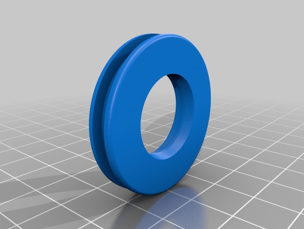
longshot plunger head 3D Print Model
Summary
for a longshpt plunger tube it goes over the stock retaliater plunger head -
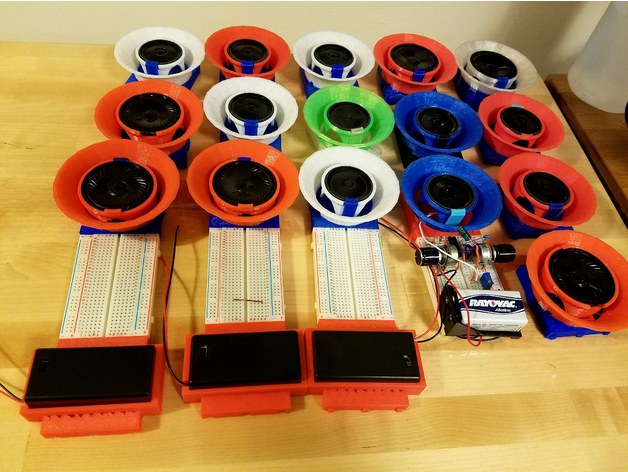
Breadboard 9V Battery Box 3D Print Model
Summary
This thing fits a 9V Battery Box (with the cover removed) to a standard breadboard. Because the breadboard is made of soft plastic, its dovetails do not provide a bomb-proof fit, but it’s good for keeping your battery from flying around. The battery box makes a friction fit with the holder. Since it does not require the cover to be fitted, some cheaper, fatter 9V batteries can be used. Use it with your favorite prototype circuit, like the Atari Punk Console. Also see my breadboard speaker amplifier. -
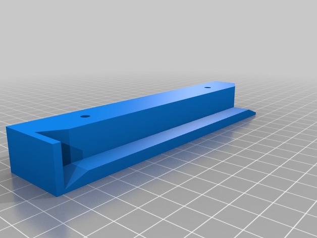
Slim Wireless Keyboard Rack with backstop – Remix 3D Print Model
Summary
The original design my user ‘drou’ inspired me to create a simple variation for a project at my office. The intent was to truncate the height of the rack to accommodate a slim keyboard design. Second, I needed a stopper at the back of the rack in order to keep the keyboard from pushing all the way through and falling out the other side.
There is only one file, simply mirror this STL for the other side of your keyboard rack.
Will get some finished photos uploaded.
Original thing: https://www.thingiverse.com/thing:1456347/
Print Settings
Printer:
Anet A8
Rafts:
No
Supports:
No
Resolution:
.1
Infill:
10%How I Designed This
TinkerCAD -
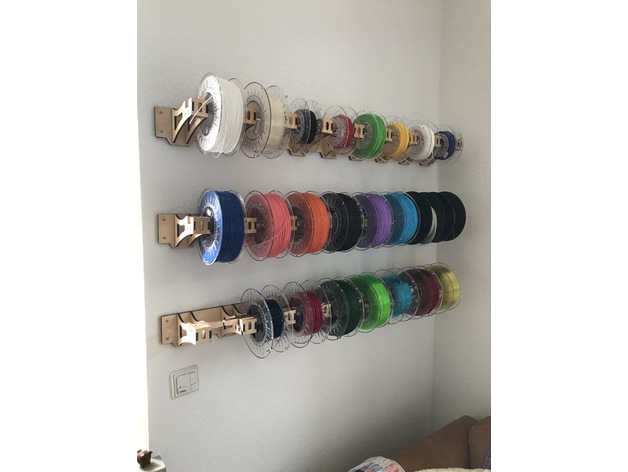
Laser cut Filament Rack 3D Print Model
Summary
This spool holder was designed in Fusion 360. It is made to hold 8x 20cm diameter spools. Plywood should be 6mm thick for optimal fit! -
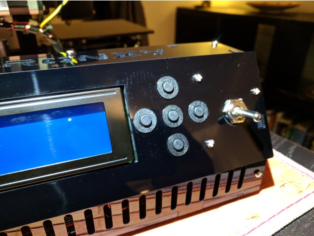
Tronxy X1 Buttonsleeve 3D Print Model
Summary
The TronXY X1 buttons tend to tlt because of the large frontpanel-holes.
These sleeves support and center the buttons. -
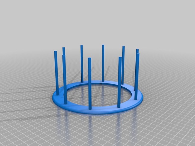
Paint rack for cosplay fingers 3D Print Model
Summary
This was a rack I made for painting cosplay fingers. Holds 10 parts. You can hot glue some mid finger parts to the rack. -
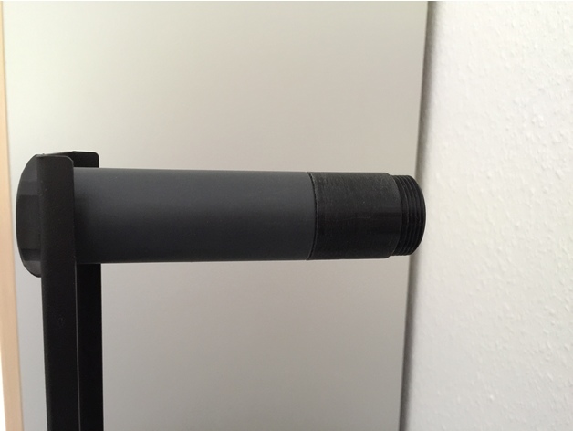
Filament holder extension 3D Print Model
Summary
Just an easy extension for the existing filament holder of the Ender 2. The fialment spool width could now be around 100mm thick. Print and screw it on.
Print Settings
Printer:
Ender 2
Rafts:
No
Supports:
No
Resolution:
0.1
Notes:
Wall 5x should be great. Layer high only 0.1
Fit to the existing filament holder. Nothing to change. Printed with PLA black. Be sure your dimension settings from the printer are correct. -
Remote Control Holder 3D Print Model
Summary
Remote Control Holder I designed to attach to a glass patio/garden table I have in the lounge. You might find other uses for the clips or the base. I recommend printing it The holes in the bottom of the base are just in case you put something in like a phone and can’t get it out from the top. My iPhone 7 is about the perfect size to get stuck, hence the holes. LOL.
Print the clips with 3 perimeters and 50% infill with a 20 perimeter zero offset brim.
Print the base upright, with supports under the base, and a 20 perimeter zero offset brim to avoid warping. The large support area should be one solid layer for the base layer, then 10% infill from there on out.
Holes in the clip and base are to stop it sliding if the fitment isn’t tight enough. Just add some short self tapping screws or bolts of 3mm wide and about 10mm long.
Print Settings
Printer Brand:
Creality
Printer:
CR-10
Rafts:
No
Supports:
Yes
Resolution:
0.2mm layers
Infill:
10%
Notes:
Made with 123D Design Version 2.1.11 from Autodesk. Because I’m too broke to afford Fusion 360. Doh!!!
Yeah I don’t even update it because I like it working in offline mode. -
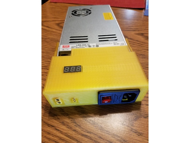
End cap for Meanwell LRS-350-12 3D Print Model
Summary
Wanted an end cap for my meanwell that would allow me to easily disconnect my Ender-2. The xt60 and xt30 just push in and are a tight enough fit that they shouldn’t go anywhere but you can always add a drop of glue to them. Links for the parts I used are below.
Voltmeter:https://www.amazon.com/gp/product/B00C58D47G/ref=oh_aui_search_detailpage?ie=UTF8&psc=1
IEC socket:https://www.amazon.com/gp/product/B01LYMNQ2L/ref=oh_aui_search_detailpage?ie=UTF8&psc=1
XT60:https://www.amazon.com/gp/product/B073QJWVVK/ref=oh_aui_detailpage_o00_s00?ie=UTF8&psc=1
XT30:https://www.amazon.com/gp/product/B074S7NH3H/ref=oh_aui_search_detailpage?ie=UTF8&psc=1
Power Cord:https://www.amazon.com/gp/product/B005VULXA0/ref=oh_aui_search_detailpage?ie=UTF8&psc=1
Meanwell LRS-350-12 Power Supply:https://holiday.lighting/psorderform
Print Settings
Printer:
Ender-2
Rafts:
No
Supports:
Yes
Resolution:
0.28
Infill:
20
Notes:
Supports only needed on the hole for the voltmeter -
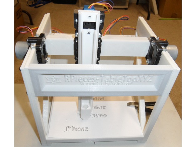
RPieces-TableTopXYZ-V2 3D Print Model
Summary
This is Version 2.0 – See Project location at
https://github.com/TGit-Tech/RPieces-TableTopXYZ
Demonstration Video @ https://www.youtube.com/watch?v=2BT0keDggYo
Version 1.0 @ https://www.thingiverse.com/thing:2166533
Estimated cost $33.93 -
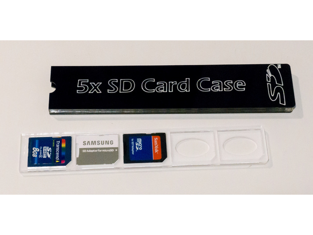
Laser Cut 5 SD Cards Storage Case 3D Print Model
Summary
Laser Cut and Engraved SD Card organizer storage box. Holds 5 SD Cards, looks great.
Assembly requires some acrylic adhesive (Weld-on #16).
Cut main SD Card slot holder from 1/8″ acrylic (card_slots.dxf)
Cut main case body from 1/4″ acrylic (enclosure.dxf)
Cut Card Slot Holder bottom from 1/16″ acrylic (card_bottom.dxf)
Cut two covers from 1/16″ acrylic (enclosure_covers.dxf)
Clean parts with alcohol prior to gluing.
First glue Card Slot Holder bottom to Card Slot Holder. Makes sure edges are even.
Now glue one of the main covers to main body. Use Card Slot Holder as a guide, but be careful not to glue it accidentally to edges.
Check fit and finally glue second main cover to main body.
Engraving (optinal):
Align complete enclosure in laser and engrave with text of your choice or included “engraving.dxf” file. Use “cut” setting at low power and high speed to “scratch” engraving on acrylic. You don’t want to cut it thru, but also grooves need to be deep enough for paint to stick.
Rub some white acrylic pain into engraving, let it dry a little and wipe it off.
Repeat until enough paint filled the engraving. Wipe again with slightly moistened rug. -
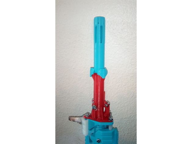
Cealyn the Caliburn – Scar Barrel Reinforcement 3D Print Model
Summary
The retaining arms on my Caliburn SCAR Barrel broke on my first print, and started to weaken on my second, so I made a quick reinforcement piece. This not only helps to hold the retaining arms so they will be less likely to break, but it makes the whole SCAR barrel operate a little more tightly.
I included an obj, which should hopefully be set up correctly, but I am unsure as I model in Blender.
It is good fodder for visual modifications, as it does not have to twist, and sits on top of the barrel.
Enjoy, and feel free to give suggestions, or remix! -
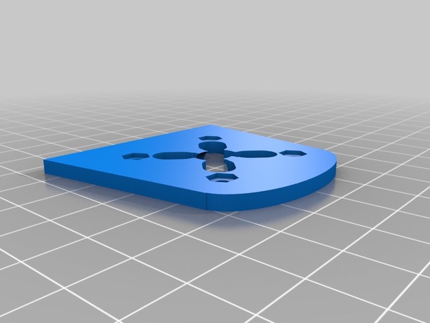
Sjywalker Falcon 3D Print Model
Summary
Some little bits for the SKYWALKER FALCON that i needed,
Some motor mounts, to replace the wooden one
A esc protector for the underside to protect water ingress and esc damage -
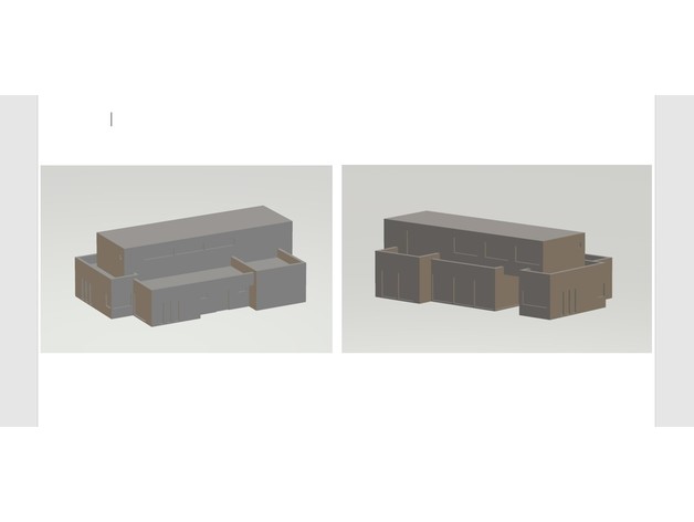
DESIGN HOUSE 3D Print Model
Summary
This is a real house in Belguim.
On the back are the coordinates.
Print Settings
Printer Brand:
Creality
Printer:
CR-10
Rafts:
Doesn’t Matter
Supports:
Yes
Resolution:
0.2 mm
Infill:
15% -
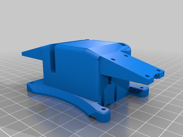
3DR Solo Retractable Landing Gear Pads w/ Payload Release 3D Print Model
Summary
This attaches to the Solo’s Accessory Bay mounting holes. It can be used with or without a small breakout board like the Brownie Boards Nano. Extra space inside can contain all the wiring.
The 9G servo slides in and is held in by the unit being screwed to the Solo.
It you remove the pins from the connectors you can push the retract wires through the holes.
The info here will help you get it wired and working.https://www.hackster.io/phantom-phreak-7ccfe4/extend-3dr-solo-accessory-bay-be4073
This is the small breakout board I like.https://store.brownieboards.com/product/3dr-solo-nano-breakout-board/
Print with supports. Doesn’t require much infill. Most of the empty space it made to hold the wires. -
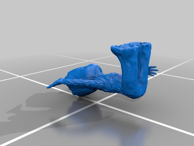
Baby Groot Sitting Waving 3D Print Model
Summary
video: https://youtu.be/nfbfa-ZI2IA?list=PLANKB9P5SKcc5wjijCna3w_mCY9xn99gL
Print Settings
Printer Brand:
Prusa
Printer:
Prusa Mk1
Rafts:
Doesn’t Matter
Supports:
Yes
Resolution:
0.2
Infill:
25% -
Soap 3D Print Model
Summary
Soap, bathroom -
Mouthpiece Remover 3D Print Model
Summary
A mouthpiece getting stuck is SOOOO annoying. Unfortunately, they cost $40 on Amazon! In preparation for the marching band season, I decided to make a cheap, 3D printed mouthpiece remover. This was made to work on trumpet mouthpiece, however it should work on most other small mouthpieces like french horn, mellophone, cornet, and fugal. In total this project cost $7 to make and 30 minutes to assemble. Total printing time was 5 hours at .1 mm with the Tevo Tornado.
How to remove a mouthpiece:
loosen the crown bolts at the bottom of the mouthpiece remover until the sliders can slide.
move the two sliders away from each other to make room form the mouthpiece.
turn the bottom wing nut on the threaded rod clockwise (bottom point of view), and alternate this process on both sides until the mouthpiece can be placed in with the sliders above the lip were the mouthpiece connects to the lead pipe.
move the sliders inwards to secure the base of the mouthpiece. Tighten the two crown bolts to lock the sliders in places.
alternate turning the top two wing nuts clockwise (top point of view) until the mouthpiece pops out. WARNING: They can really pop out quite aggressively, I’m not responsible if any mouthpiece gets dents by falling on the floor.
Here’s a video of me using it:https://www.youtube.com/watch?v=AeP1htOAiFo
Materials:
All the supplies were found at Home Depot.
1/4 in threaded rod
1/4 in – 20 nylon lock nut (2 needed)
1/4 in – 20 nut (2 needed)
1/4 in – 20 wing nuts (4 needed)
number 8-32 x 3/8″ wing/crown screw (2 needed)
number 8 metal washer (2 needed)
Assembly:
Print all the parts out (no supports required!)
Cut the threaded rod to an appropriate length (mine were 3.75 in long)
Insert the threaded rod into both the threaded holes in the top section of the mouthpiece remover to break away any lose plastic/defects in the print. Remove the rod afterwards.
At one end of each of the threaded rod, put on a lock nut. They can be twisted on part of the way by hand, but then you need to use a wrench and pliers to twist the nut until the end is flush with the rod.
Insert one of the rods with the nut into the bottom of the build. Then, put on that sides slider and hold it in with it’s corresponding crown bolt and washer.
Insert the rod into the top section of the build. Use the wing nuts and regular nuts to help twist it on (see picture for nut setup)
Insert the other rod into the other whole, again put on its wing nuts and nut to twist it in.
Put on the other slider and its crown bolt and washer and you’re done!
I designed this using fusion 360 and by looking at pictures of existing mouthpiece removers. If you enjoyed this project, a tip/like would be very much appreciated! -
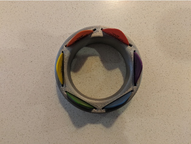
Pic Holder 3D Print Model
Summary
This is a guitar pick holder designed to hold 6 picks. The picks can be 50mm-130mm thick. You can fit 12 picks if you put 2 picks in each slot (you can only use thin picks if you want to put 2 in each slot). Print it out and show me your work!
Print Settings
Printer:
anycubic i3 mega
Rafts:
No
Supports:
No
Resolution:
Your choice – 0.1 up to 0.3
Infill:
Greater than 10%
Notes:
Print right way up in a nice bold colour. We used 3DFillies PLA+ in silver metal. The more infill you use, the more stable it is.
Post-Printing
Put picks in and rock out!
How I Designed This
Using Fusion 360 I created a circle with an inner circle. These were extruded up. Fillets were added. I then added a pick size rectangle, and then extruded (cut) it into the circle. Then I used the pattern tool to create 6 slots -
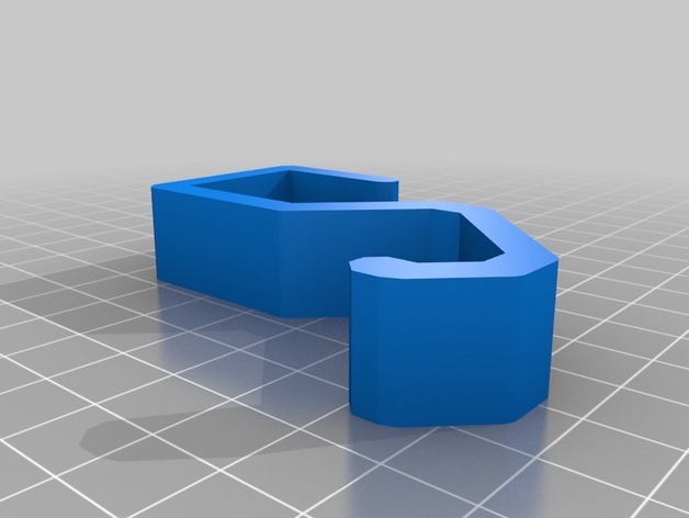
7/8″ Square Angled Shower Rod Hook / Hanger 3D Print Model
Summary
This is a simple hook I designed to hold some baskets which we use to hold my kids bathroom toys. There are many hooks and hangers available on Thingiverse. I wanted the hooks to sit out for ease of use versus just hanging down.
These hooks work very well and feel quite strong.
I made these out of PETG.
Print Settings
Printer Brand:
TEVO
Printer:
Tarantula
Rafts:
No
Supports:
No
Resolution:
200
Infill:
40
Notes:
This hook could be done in most materials. I used PETG for strength and flexibility.
Post-PrintingNotice how they hang forward, and not just down.
-
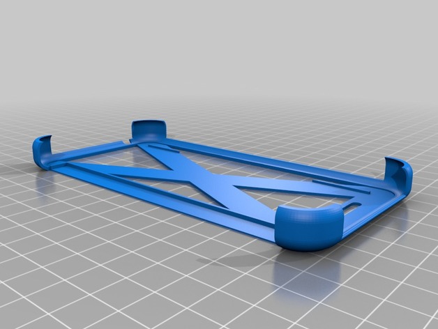
HTC 510 Dot View Solid Part V2 3D Print Model
Summary
HTC 510, Dot View, Solid Part.
Reste juste à coller ( Époxy ) la partie “Dot view”. Beaucoup plus mince et flexible que la première version.
Just stick to the “Dot view” part (with epoxy glue). Much thinner and flexible than the first version.
Print Settings
Printer Brand:
Robo 3D
Printer:
R1 ABS + PLA Model
Rafts:
No
Supports:
No
Resolution:
0.1mm
Infill:
90% -
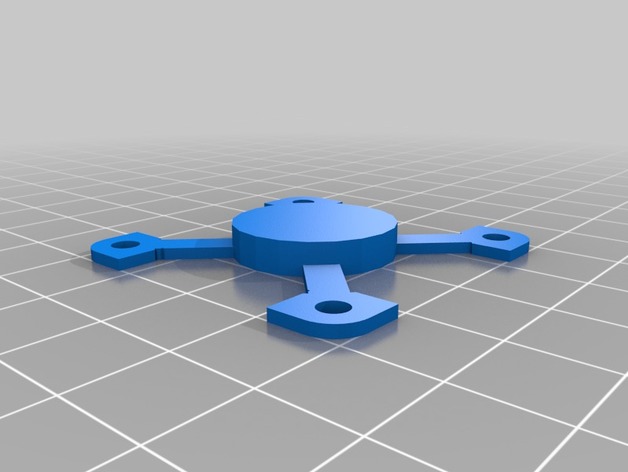
Minimalistic fan bracket / mount for 40mm fan on a nema 17 3D Print Model
Summary
I wanted to put a fan to a drive motor (nema 17), but do not have a lot of space for it, so I created this minimalistic fan bracket. Not ideal in any way, shape or form, but it does provide some cooling when there is little room for a fan.
Mount the bracket to a 40mm fan and glue the centre part with CA glue to the motor. Nothing more to it.
Print Settings
Printer:
Heavily modified mendelmax 2
Rafts:
No
Supports:
No
Resolution:
.250
Infill:
lots of it
Notes:
Print using a strong material and with lots of infill, since the arms are flimsy and need all the strength they can get. -
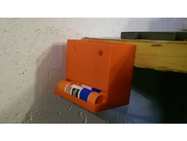
Glue Storage Bin 3D Print Model
Summary
Storage bin for 6g glue sticks. Will comfortable hold 7 glue sticks. Has two threw holes in front to access the counter sunk mounting holes in the rear. -
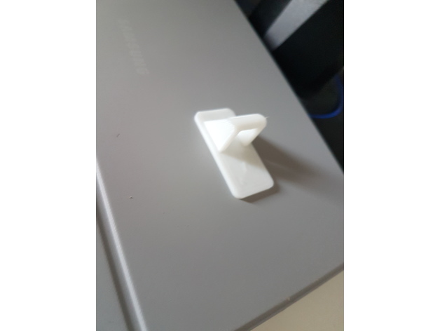
Glasses holder 3D Print Model
Summary
Glasses holder
Print Settings
Printer Brand:
Creality
Printer:
CR-10
Rafts:
No
Supports:
No
Resolution:
0.15
Infill:
10% -
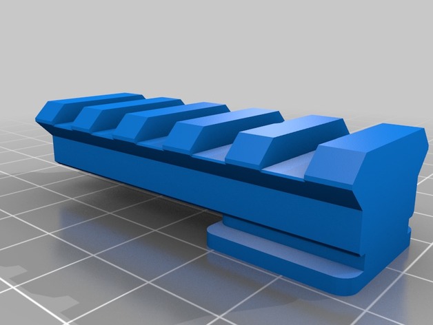
NATO/Picatinny Rail for Hot Shoe 3D Print Model
Summary
NATO Rail for Camera Hotshoe, for example to mount Red Dot/Reflex Sights to a camera.
Picatinny/Weaver compatible
Precise and tight fitting to ensure it is stays accurately aligned.
No moving parts that could be knocked out of alignment.
Includes FreeCAD source file in case you’d like to make your own adjustments. -
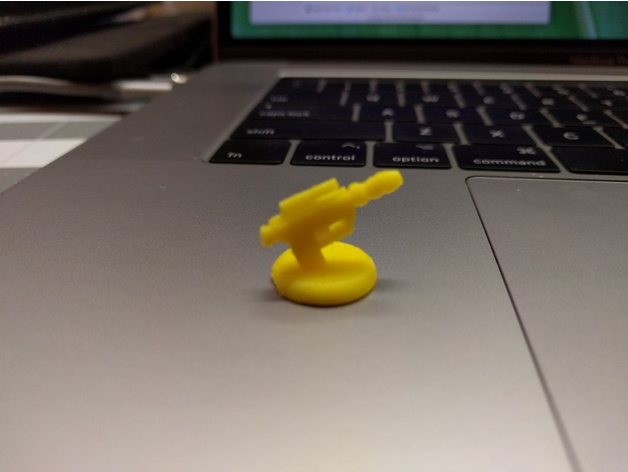
Twilight Imperium Shock Troop 3D Print Model
Summary
Shock troop for Twilight Imperium adapted for fused filament fabrication printers. See print settings for details.
Print Settings
Printer Brand:
PowerSpec
Printer:
Duplicator I3 PLUS
Rafts:
Yes
Supports:
Yes
Resolution:
0.1mm
Infill:
100%
Notes:
Supports from build plate only with 40deg support overhang (Cura) -
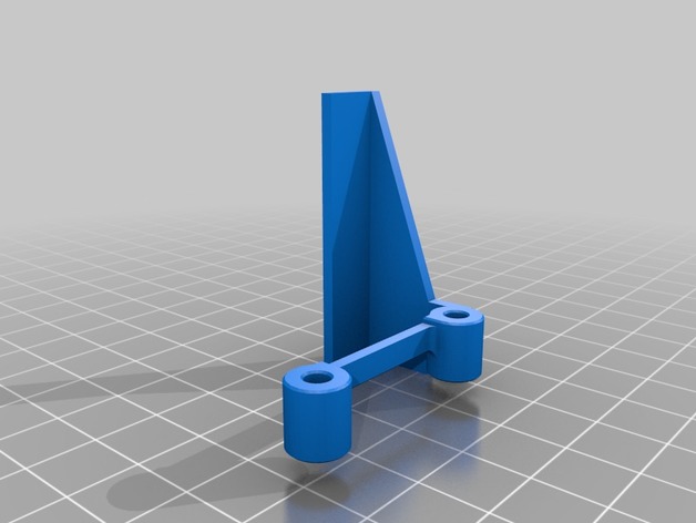
Cooling Fan Spacer for A6 with lights 3D Print Model
Summary
The original fan spacer works great. I wanted some light down by the print nozzle, so I could watch the print without using a flashlight. I modified the spacer to add an area for LEDs. I stuck a small strip of LEDs on and wired them into the extruder fan power.
I’m quite happy with the result. Soldering into the existing fan wiring (while it was still on the printer) was a bit of a PITA. I didn’t want to completely undo the loom and remove the fan from the printer, so that’s how it had to be. Still, well worth it.
Print Settings
Printer:
Anet A6
Rafts:
No
Supports:
Yes
Resolution:
.2 mm
Infill:
100%
Notes:
I printed at 100% infill. Once you print the walls, there’s not much left on the inside I figured why not. Print with supports and a brim. Print in the orientation shown on the model here. Its minimal support and it comes off very easily.
Post-Printing
LEDs
I bought a meter long strip of 12v LEDs for about $1. I cut off a 45mm section and attached it to the bottom of this part. I soldered on servo wire, and then soldered those wires to the power leads going to the extruder fan. For extra security, I put some Kapton tape around the LED strip as well (also to cover up the exposed solder points). -
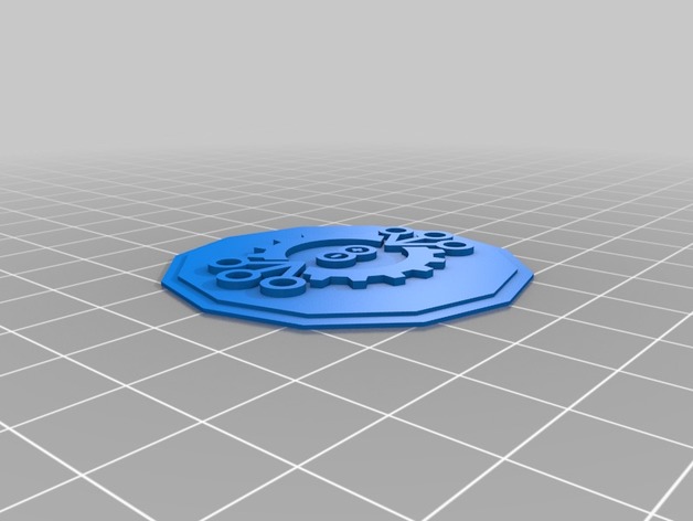
Medalla Liga de Robótica Chile 3D Print Model
Summary
Medalla hecha con el logo de la liga de robótica Chile. -
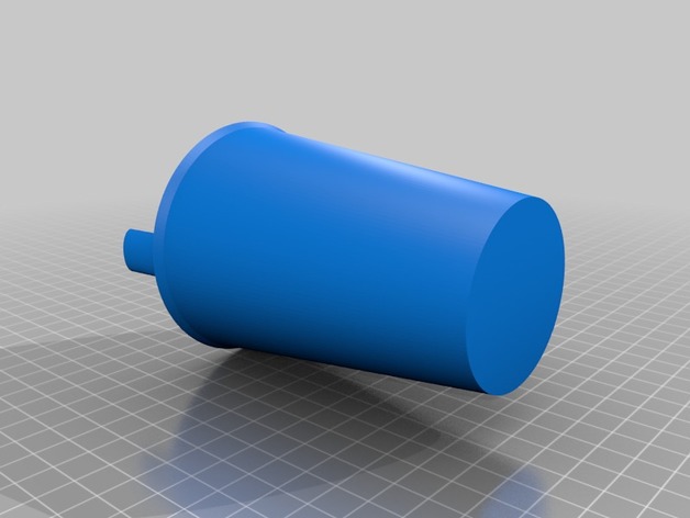
Childrens’ cup with built in straw 3D Print Model
Summary
A small cup with a built-in straw for easy drinking. Make sure that you use a food-grade safe type of plastic like PLA. -
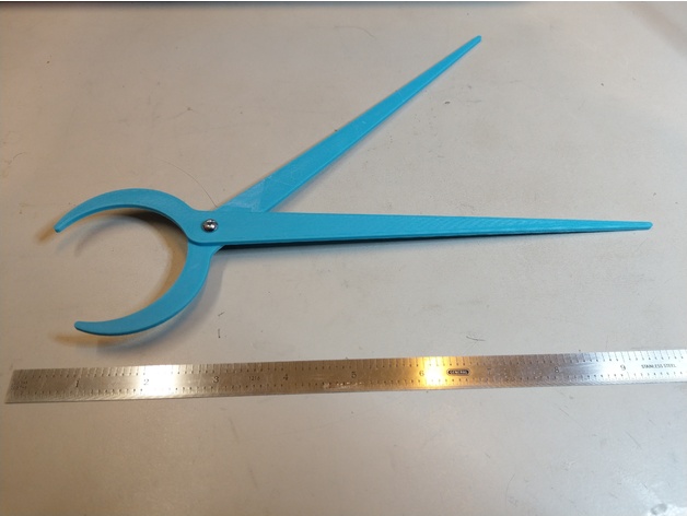
Pi Divider 3D Print Model
Summary
This is a tool for correctly sizing a collar to roll up a cane mat in glassblowing. It operates like scissors, and the lengths are sized so that the larger opening is always pi times the length of the smaller opening. This means that when you lay out your cane and open the long, straight side to the width of the cane, the smaller curved ends are the perfect collar size. You’ll have to use a metal caliper for on-the-fly sizing since the plastic will melt if it comes near the hot glass, but this tool will show you exactly what size to set them at.
Chances are if you’re searching for a pi divider, you already knew all that. If you didn’t, search for videos of the ‘reticello’ process and you’ll see why this is useful.
Note that you can size this yourself using Fusion 360 and the .f3d file. See below section for important notes.
Print Settings
Printer Brand:
Prusa
Printer:
i3 MK2S
Rafts:
No
Supports:
No
Resolution:
200um
Infill:
20%
Notes:
If the ends start to peel up, use a 5mm raft (brim).Changing the Parameters
The .f3d file includes two user parameters, Length and HoleD. The diameter of the hole can be changed to suit whatever fastener you want to use. The overall length can also be changed based on what you need, and everything else (except for the hole diameter) will scale accordingly.
HOWEVER there’s a quirk in one of the sketch arcs that causes it to invert if the Length parameter is changed by too large an increment. So if you want to increase/decrease the overall length, make multiple changes in 1-inch (or even 0.5 inch) increments to avoid the arc problem. If you have any problems, leave a comment and I’ll respond.
Happy printing! -
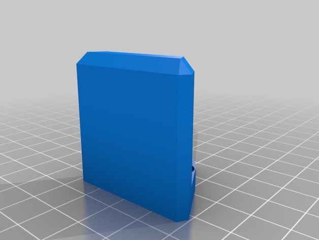
AXA Tool Holder Holder 3D Print Model
Summary
Simple AXA Quick Change tool holder, uses 2 drywall screws
Print Settings
Printer:
cetus
Rafts:
No
Supports:
No -
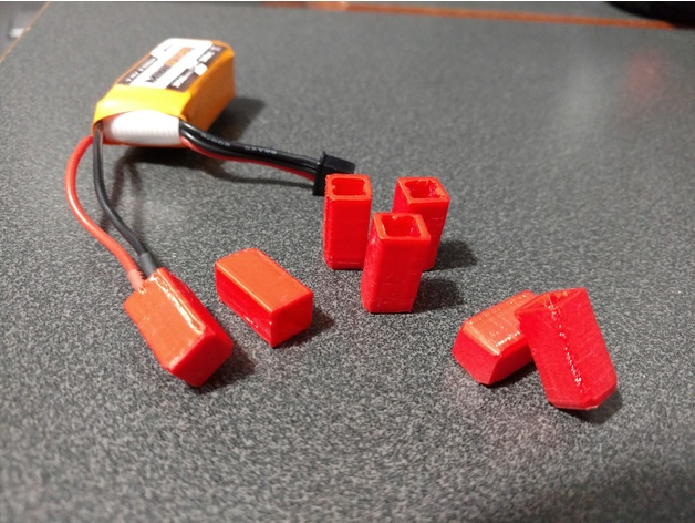
Deans Micro Cover 3D Print Model
Summary
I’ve never had any of my batteries short before in my storage case, but due to the connector’s hermaphroditic design, there’s always that possibility, so I designed this cover which snaps over the connector to protect the exposed pin.
This part was designed for and REQUIRES printing using FLEXIBLE filament.
Print Settings
Printer Brand:
Prusa
Printer:
Prusa Mk2
Rafts:
No
Supports:
No
Infill:
100%
Notes:
Use flexible filament. Print with a brim for maximum bed adhesion. -
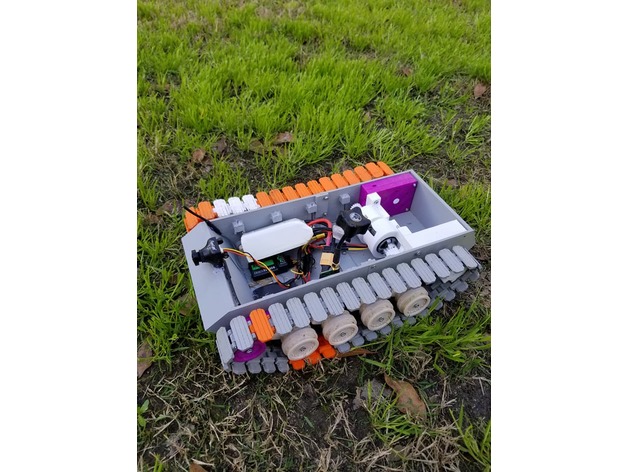
OPEN QUAD TANK 3D Print Model
Summary
OPEN QUAD TANK
I have been working on this for a while in my free time, but my work has brought me to South Korea for a few months and I cannot continue designing with my current computer and lack of printer. This needs a lot of love and members of both the FPV and 3d Printing community have expressed interest in turning this into a group project, and I am excited to see how awesome we can make this together. Please post makes
All files are of my own design at the time of posting and I permit them to be modified, copied, and used but not sold. All content and creations added by other makers is also not for sale.
Please read the following to get up to speed on the project.
GOALS
MATERIAL CONSIDERATIONS
HARDWARE
SETUP
DESGIN FLAWS / TO DO LIST
HOW TO HELP
Many creators inspired this project and taught me what I needed to get this far, some are listed here.
Please check their YouTube channels to support them
-Daniel Noree
Thomas sanladerer
Aloha FPV
Kalani J
Flite test
3D printing NERD
All files are of my own design and I permit them to be modified, copied, and used but not sold.
Primary Goals of this project
1.HAVE FUN
Should be printable on cheap printer such as Wanhao i3, other i3 clones, cr-10s, and other printers with similar build volume
Should use parts common to FPV mini quads
Should not rely on exotic materials (nylon would make the gearbox easier to design but we want everyone to be able to print this)
Should maximize printed parts and eliminate purchased hardware whenever possible to KEEP IT CHEAP
-Printing material suggestions for current files
Everything COULD be printed in PLA, but the gearbox would need heavy lubrication before running. Also using a 3s battery would increase survivability as well.
I suggest PEGT be used for the gearbox and all load bearing parts due to its flex before breaking properties and higher resistance to heat
-Hardware used
An assortment of M3 screws, lots of them
1” 16 or 18 ga finish nails for tracks (ill try to clear this up)
Bearing 3x8x4 3mm hole 8mm tall 4mm thick
Bearing 10x15x4 10mm hole 15mm tall 4mm thick
Xm20 escs x2 or any miniquad ESC capable of 3d mode on BLheli
PDB, one with current sensing and osd would be best
RC radio with receiver capable of PWM (one with pins for each channel) not SBUS
Wire an heatshrink
Xt60 connectors
MOTORS- currently using NTM propdrive 2826 1200KV/ lower KV would be better for the current gearbox
FUTURE MOTOR OPTIONS- hopefully going to design gearbox for use with 22XX miniquad motors which produce 100-200 more watts of power than the NTM motors even with the size difference.
For FPV use the following
runcam 1177 (I use the OWL for night drives)
200-600mW VTX (600 allows me to sit on my couch and drive around my brick house
Any FPV goggles
-SETUP FOR CURRENT FILES
Flash escs on BLheli to 3d mode with center stick begin no throttle (this allows for forward and reverse, if you don’t have escs that do 3d mode you will only have forward on each track)
Connect each esc to the PDB as usually for miniquads
Connect the signal wires to receiver on the elevator and aileron channels (you may need to solder on some old school PWM connectors
Connect the 5v out and ground to the receiver using PWM connector
Wire a battery lead to the PDB
USE 2-4s If you get strange results with the lower voltage, try to up the start up power of the ESCs in BLheli. 4s usually works just fine but 2s gave me issues
Program your radio
You want to use elevon mixing, look it up on youtube. You may have to do both between channel mixing and swapping the connectors on the receiver to get everything going in the right directions.
Reduce your rates to 60% or less on all channels if using 4s. increasing this value will make your tank faster but I began to break PLA parts at 65%. Stronger designs and PEGT tracks may allow for higher rates on 4s
-Problems with the current design in order of severity
no front wheel tensioner makes the track jump off regularly on slow turns
Fix- design and add tensioner
PLA tracks break at the joint
Fix- print in PETG / increate tempt and extrusion multiplier on PLA/ in cad software increase material at weak point
suspension incomplete
Fix design suspension / or just glue suspension arms in place for now (I used hot glue)
gearbox uses uncommon motor
Fix increase gear ratio to 18:1 for 2300kv motors and redesign motor mount
no top
Fix Design any top you like and share (I want to see a T34-85Print Settings
Printer Brand:
Wanhao
Printer:
Wanhao Duplicator i3 Plus
Resolution:
.2-.25
Infill:
depends
Notes:
USE high at least 4 walls and high infill for the gears on other load bearing parts.
Print the drive shaft horizontally or it will sheer off if printed vertically
make sure to rune the gearbox by hand and oil before using motors -
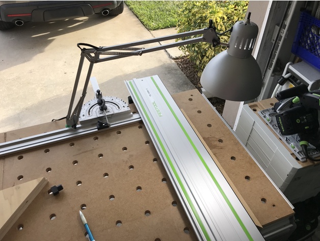
Tertial MFT Dog 3D Print Model
Summary
A bench dog for a FESTOOL MFT (19.81mm) which has a 13mm hole in the middle to accept an IKEA Tertial lamp stem.
Print Settings
Printer Brand:
Prusa
Printer:
i3 MK3
Rafts:
No
Supports:
No
Resolution:
0.2mm
Infill:
20%
Notes:
Should be an easy print, be sure to print from inside out for a better fit and finish in the dog hole.
How I Designed This
Fusion360 -
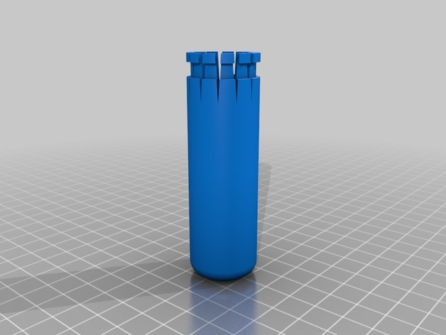
Gear selector extension for BMW K1600 GT GTL 3D Print Model
Summary
With quick shifter gear, the foot selector is to short on BMW K1600.
This print fix the problem. Just squeeze it with a 5 mm zip tie.
Print Settings
Printer Brand:
Prusa
Printer:
i3 MK3
Rafts:
No
Supports:
No
Resolution:
0,20
Infill:
20 %
Notes:
4 perimeters layers
PLA -
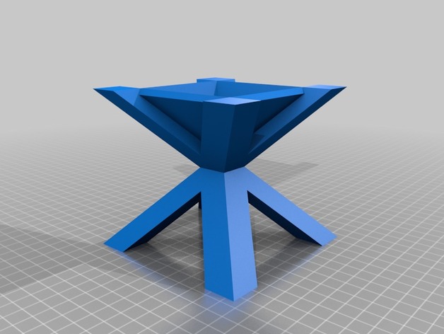
Crisscross Planter 3D Print Model
Summary
This is a new planter that I came up with for your cactus or succulent. I have yet to try and print my designs but they all should work if your printer is well calibrated. Overhangs should not be too extreme but will test your machine for sure.
This one will work even if you cut it in half!
If you want to modify it let me know I can provide the CAD files. -
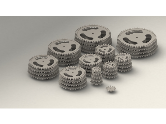
Gear Collection 1 3D Print Model
Summary
Spur Gear Collection 1
Module – 10 mm
Pressure Angle – 20 deg
Teeth – 10 to 50 (Total 41 gears)
Gear face width – 15mm
Shaft hub size – 20 mm default.
If gear stl file name is Spur_Gear_10M_10T.stl then the gear has 10 teeth with module 10
Spur gear Collection 2 – https://www.thingiverse.com/thing:2817682
(Collection 2 contains teeth from 51 to 100)
Module = (Pitch dia /Number of teeth)
If you want different gears with module and teeth tell it in the comment section -
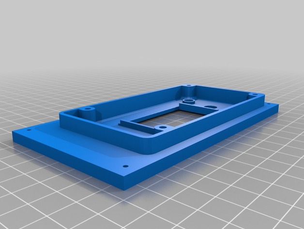
MKS MINI PANEL REMIX 3D Print Model
Summary
Remix to make a plate cover for my d-bot corexy printer. -
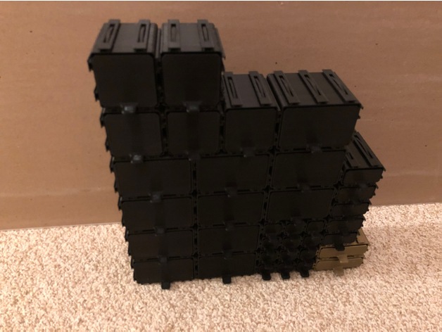
Parts Drawers 3D Print Model
Summary
This is a set of modular drawers which interlock and are infinitely expandable. The basis of this design is to produce drawers that can be printed at high extrusion speeds and will fit together without tolerance issues. The system uses regularly spaced T slots with ample clearance to fit together loosely and built in springs to provide friction to keep the drawer boxes aligned. The system also uses a small beam across the top of the drawer body which acts as a drawer stop to limit the drawers travel as well as to reinforce the top of the drawer box if loaded (In practice the number of spring loaded T joints tends to distribute the load well). Larger drawers have thicker walls than smaller drawers for increased strength. The drawers are based on 1″ increments. The smallest drawers are 1″x1″ however the larger size drawers are really based on 1″+ the joint thickness.
I have already revised the design a bunch of times to make things run fit together nice and to get the slots to fit easy but hold where you place them, I will be interested to know if they work as well as they do for me for others.
One further note. This is based on a parametric model so that I could get different drawer sizes easily and control tolerances and wall thickness via spreadsheet. Based on the way it is made if you print the drawer dividers they will need to be rotated to lie flat on the printer bed. The drawers and boxes should load in the correct orientation to print.
Print Settings
Printer Brand:
Ultimaker
Printer:
Ultimaker 3
Rafts:
No
Supports:
No
Resolution:
.2mm
Infill:
30% (only the drawer catch gets infilled)
Notes:
Printed in PLA and PLA+. Sliced in Cura Printed at 100mm/s on 60C borosilicate glass covered in Aquanet hairspray. Usually the drawers fit together just fine, sometimes I get a little bit of stringing if I rush things too much but just running the T slots together a few times makes everything smooth. -
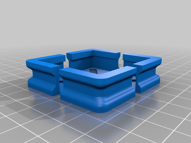
Glass Plate Corner Brackets for Flashforge Inventor 3D Printer (Remix) 3D Print Model
Summary
These corner brackets were designed to interface with the Flashforge Inventor 3D printer and the glass plate upgrade from Flashforge USA. Supports glass dimension (L x W x H) 9 x 6 x 0.15 inches. Glass must be installed on top of the Flashforge build tape and aluminum build plate. You may require four washers to prevent the hex nuts from going through the gaps of the corner brackets.
The corner brackets are designed to be of sufficiently low profile to accommodate the build plate movements in proximity of the internal filament spools. The corner brackets can be fastened using the existing build plate hardware and are flush with the surface of the glass.
I would like to say that this project worked on the first attempt but it would be false. What started as a deliberate design attempt turned into a series of trial and error. It took me seven versions to get it right.
Print Settings
Printer:
Flashforge Inventor
Rafts:
No
Supports:
Yes
Resolution:
0.08mm
Infill:
100%
Notes:
In order for these brackets to work at bed temperatures up to 110 degrees Celsius, I recommend using Proto-Pasta Carbon Fiber HTPLA for printing these and then following directions from Proto-Pasta for annealing. I do not recommend the use of regular PLA or ABS for this project as they will become soft and rubbery during heated bed operation.
To ensure compatibility with your system, here are the measured dimensions of the parts that the brackets interface to:
Original Aluminum + PCB + Tape Build Plate (L x W x H) 232 x 153 x 8.25mm
Glass Plate Upgrade (L x W x H) 229 x 152.45 x 3.8mm
I recommend tightening the nuts once the build plate is fully raised and pre-heated to 60-70 degrees Celsius.
How I Designed This
Step 1: New Enhancements
After having used the source version of these for two months, I discovered some areas for improvement. I increased the height of the opening that interfaces with the “Original Aluminum + PCB + Tape Build Plate” by 0.2mm in order to get an even better fit. I also reinforced the external sides of the corner brackets as they seemed to start warping slightly at 110 degrees Celsius (even with the annealed Proto-Pasta Carbon Fiber HTPLA). I think that with the thicker material, which is an insulator, the part should maintain its shape. This is still a work in progress in that I have not yet printed it to verify the fit and conduct some testing; I plan on having it verified and tested next week. -
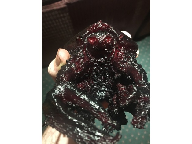
Garthim Warrior 3D Print Model
Summary
Deep within the castle of the Crystal in the world of Thar, the curl and twisted Skekis took control and slowly drained the world around them. As dark and wicked as these creatures were, what they created within the bowels of the castle, would go on to spared terror and destruction for many years. The Garthim solders, were the main enforcers of the Skekis’s will.These imposing figures were not only built for strength but for speeds as well. Massive, unyielding, merciless, virtually indestructible, and always in vast numbers, these monsters would aid their masters in ravaging the land and leaving little in the wake, and whatever or who ever they didn’t destroy they often captured and dragged back with them to the castle, never to be seen or heard from again.
I was actually shocked when I realized that no one had tried to created a 3D print of these guys yet. I grew up with a weird relationship with them and loved to fear them, which later turned into a fascination. This model was based of of some still images and some original concept art made by Brain Froud. I also got some inspiration from this much better version by SeithCG (which you should totally check out).
http://seithcg.com/wordpress/?p=1195
This first version still has a few issues to work out with the legs but it still stands by itself. Hope you all enjoy it as much as I do.
Print Settings
Printer Brand:
FlashForge
Printer:
Dreamer
Rafts:
No
Supports:
Yes
Resolution:
.20mm
Infill:
10%
Notes:
print at a slow speed and use as little supports for the lower legs as possible. -
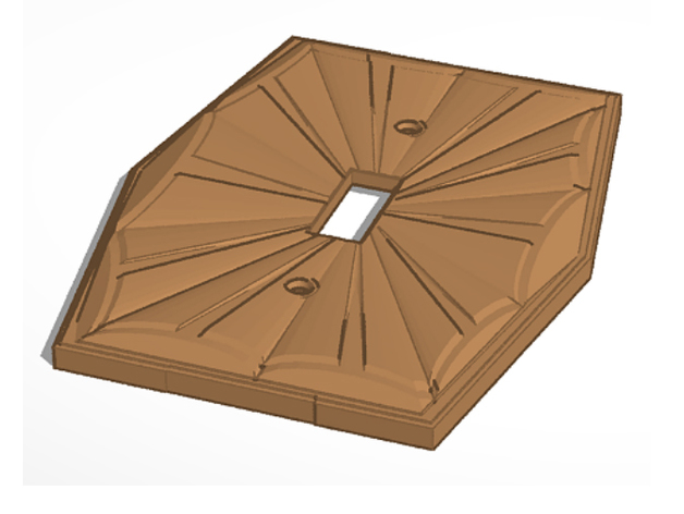
15 Types Vintage Retro Sunburst Lightswitch Cover Wall Plate 3D Print Model
Summary
Lightswitch Cover based off a vintage midcentury brass design, with multiple iterations to fit most modern switches, plugs, and dimmers. Needs to be printed with supports. -
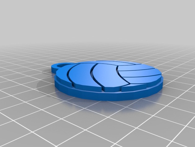
Volleyball Name Tag 3D Print Model
Summary
A keychain that has a place on the back for the players name and number. Print in one color or change the color of the middle piece to add an outline. -
Cargador 380cc 3D Print Model
Summary
Cargador 380cc
Con y sin soporte conector go pro. -
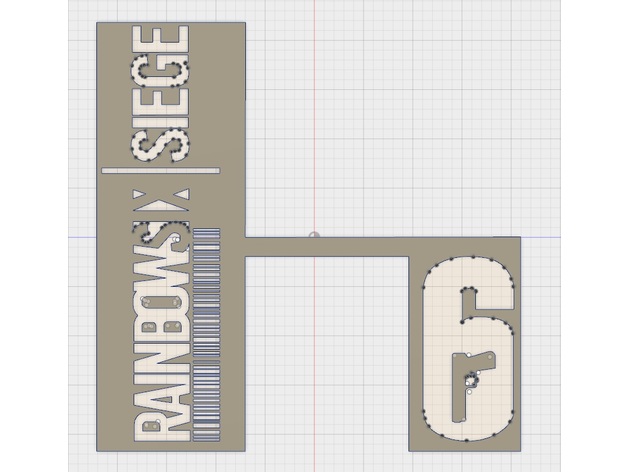
Rainbow Six Siege Logo Template 3D Print Model
Summary
This is a template I made with the Rainbow Six | Siege Logos. The model is meant to be scaled in the slicer software (at least in Cura) to fit whatever needs necessary. It is a template so everything is pretty much self explanatory. I used this on a Alpha Pack prop I made so that’s why the logos are arranged the way they are with the inclusion of a “barcode”.
Disclaimer: I do not claim to own the Rainbow Six | Siege logo or the rights to it.
Print Settings
Printer:
Monoprice Select Mini v2
Rafts:
No
Supports:
No
Resolution:
Doesn’t matter
Infill:
10% (Doesn’t matter) -
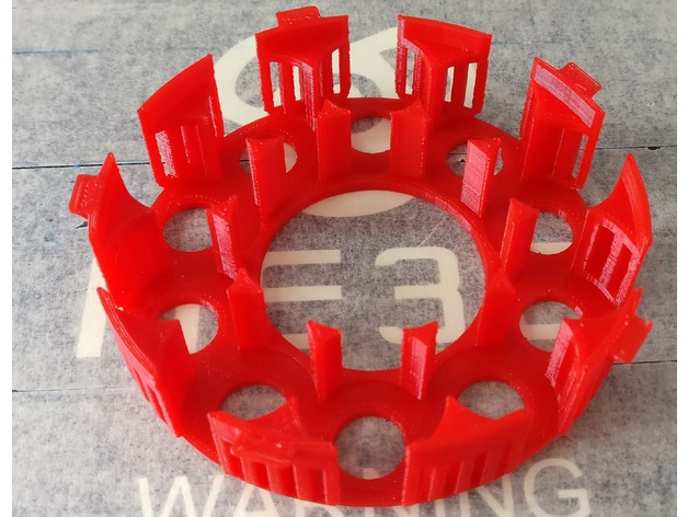
Betrayal at House on the Hill Token Organizer Bottom (lite) 3D Print Model
Summary
I removed some materials from the original version. Still seems pretty tough. Printed using 0.3mm resolution. -
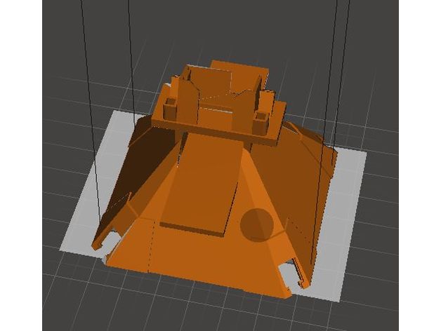
UDI U818A Cover with Camera Stand 3D Print Model
Summary
This is a remix of thingiverse UDI U818A Cover Mod.
Print Settings
Printer Brand:
MakerBot
Printer:
MakerBot Replicator 1
Rafts:
No
Supports:
No
Resolution:
0.2
Infill:
Not Applicable
Notes:
Printed on a FlashForge Creator Pro 2016 model. The corners are reinforced to improve attachment. This cover is modified to hold a whoop camera. -
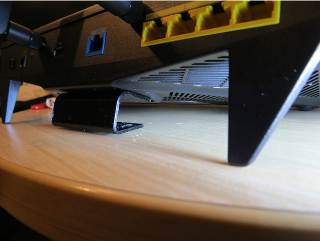
Synology RT2600ac Wall Mount Adapter 3D Print Model
Summary
Lovely router by all reports (I haven’t actually set it up yet), but the steep angled legs make the built-in mounting slots rather ridiculous. They’re an inch away from the wall and tilted at about a 26-degree angle.
CAUTION: Synology’s instructions for this router say simply to place it on a flat surface and make no reference to the keyhole slots underneath. There is also a safety note, “Place the product right side up at all times.” Possibly I’ll have gone to all this trouble just to cook my router. I doubt it, but if yours overheats and you think it was because you put it on the wall, do let me know!
(I have so little flat surface available between computers, ink printers, 3D printers, a solder rework station and bookshelves, I’m willing to risk it.)
Print Settings
Printer Brand:
Prusa
Printer:
i3 MK2S
Rafts:
No
Supports:
Yes
Resolution:
0.20mm
Infill:
100%
Notes:
To avoid strain along layers, I rotated it to print standing tall with a 2mm brim. (See the PrintSetup.PNG screen capture.)
Make sure that the axis along which the little pins extend is your X or Y as printed, not Z, or the layers and the pins might detach under strain.
Post-Printing
Try #6 screws to mount it. #8 screws are a bit too large. I put the keyhole slots 2″ apart.
How I Designed This
Mostly just trial and error. Third try was the charm. I’m puzzled by the fact that according both to my digital caliper and the values I had to put into FreeCAD to make it work, the centers on the router’s mounting slots are about 2.06″ apart. That doesn’t even make sense as ~52.3mm. -
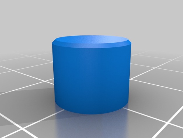
EleksMaker A3 Pro – On/Off Switch 3D Print Model
Summary
ON/OFF switch for EleksMaker A3 Pro
This is an on/off switch for the EleksMaker A3 Pro.
When I received my A3 Pro, the button in the bundle for the control board was round, which was fine, but the switch on the board is actually square, so it wouldn’t fit. Thus I made this.
Print Settings
Printer Brand:
Creality
Printer:
CR-10S
Rafts:
No
Supports:
No
Resolution:
0.4mm -
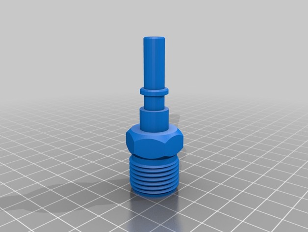
Nebia Shower Wand Connector to 1/2″ BSP Adapter 3D Print Model
Summary
An adapter that changes Nebia’s proprietary shower wand connector to a standard 1/2″ BSP connector.
Note that the water temperature between the Nebia shower head and the 1/2″ BSP output might be significantly different, and there will be reduced water flow.
Use at your own risk.
Print Settings
Rafts:
No
Supports:
Doesn’t Matter
Infill:
100%
Notes:
Print using PETG for safety and durability. -
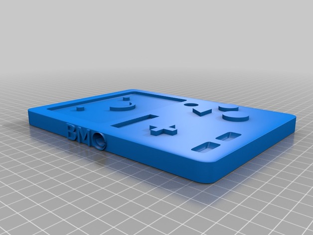
BMO Wall Hanger for Golden Sword 3D Print Model
Summary
This goes with the Golden Sword for Finn I made. The model I uploaded for the sword is designed for a kid. I enlarged it myself in Tinkercad to make it a bit bigger. If you do the same, this will work for both sizes. The arms are not perfect. I’m going to have to add some kind of filler to the nubs to make them look more smooth and fluid. the arm sockets also have extra material in them. I tried to get as much out as I could. Program is not perfect and I tried for about an hour just on one arm trying to get all that mess out. I’m going to take an razor blade to them and get the extra material out. Should work just fine. -
battery holder 18650 wismec style 3D Print Model
Summary
based on the wismec 2gen