Summary
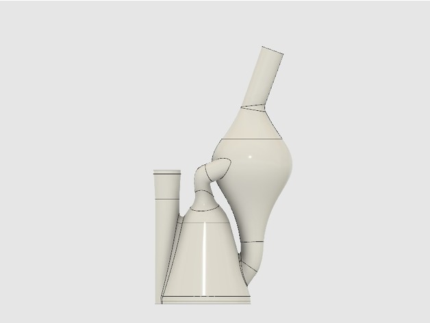
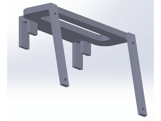
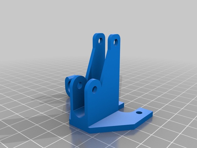
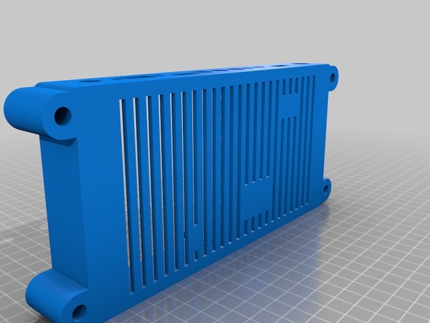
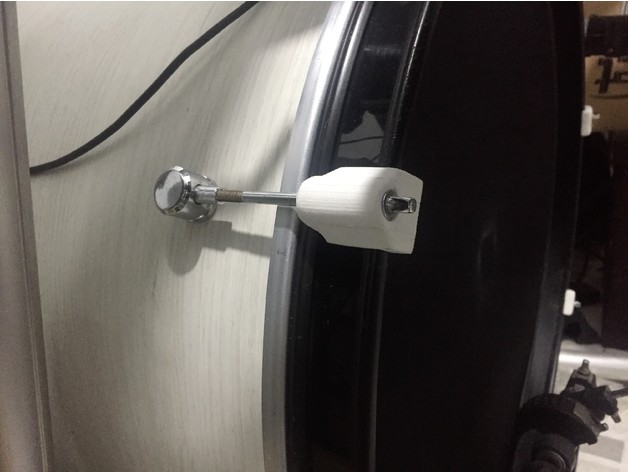
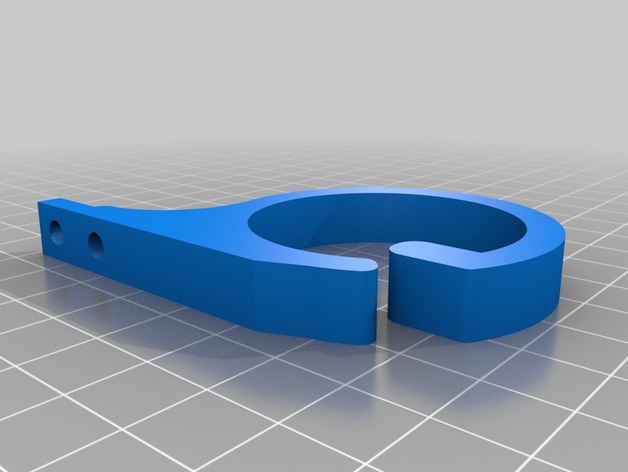
Thanks to JTM 88 for the original. I extended the base to add a second screw hole as it suited me more. Great design.
Print Settings
Printer:
ultibots d300vs
Rafts:
Doesn’t Matter
Supports:
Doesn’t Matter
Resolution:
.2mm
Infill:
50%+
Author: Thingiverse
-
Cable clip v2 remix 3D Print Model
-
Flite Test Gremlin Camera Mount For Andres Frame 3D Print Model
Summary
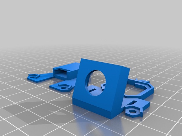
After digging around for some mounts for the Flite Test Gremlin Andres frame, I came across the perfect answer. Hackoholic published one for TJ’s frame. (Thing #thing:2311377). I started from scratch using my trusty OpenScad program. After wearing out my calipers and emptying out the coffee pot, I now have something that I think will work.
Print Settings
Printer:
MTW Minimax
Rafts:
No
Supports:
Yes
Resolution:
.15 mm
Infill:
100
Notes:
I used 100% infill and Hatchbox TPU. You would have to experiment with an infill less than 100%
Post-PrintingSide View 20 degree camera tilt
Rear 3/4 view
RX top plate for R-XSR
How I Designed This
OpenSCAD
Tell us more… -
Fu Dog concrete garden ornament 3D Print Model
Summary
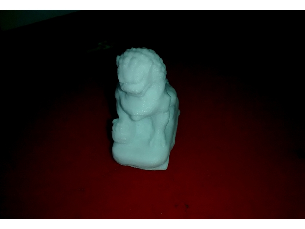
A 3D scan of a large (Approx 40cm) garden concrete ornament that has been scanned using photogrammetry and made printable using blender. -
S9 Antminer Air Duct v2 3D Print Model
Summary
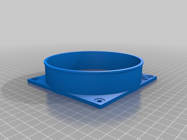
I custom made this for my S9 Antminer Farm
Print Settings
Printer:
CR10-4S
Rafts:
Doesn’t Matter
Supports:
Doesn’t Matter -
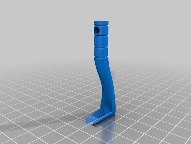
Tick Twister w/hole 3D Print Model
Summary
Simple remix to add a hole so this can be added to a key ring. -
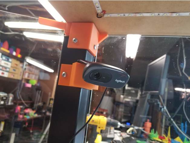
Logitech C270 Lack Enclosure Cam Mount 3D Print Model
Summary
This is a quick mount I made for a C270 cam that can screw on to one of the legs of my IKEA Lack enclosure. Screw holes are 6mm
Print Settings
Printer:
Prusa MK3
Rafts:
No
Supports:
No
Resolution:
0.2
Infill:
20% -
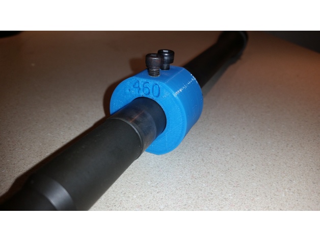
Barrel Dimple Jig 3D Print Model
Summary
Barrel Dimple Jig for .75″ gas block with .620″ hole spacing. Drill the 4 holes to 5/32″ and tap 2 top holes with a 10-32 tap. Use a cone set screw to line up and gas hole and drill the other side to dimple your barrel.
Print Settings
Printer Brand:
Robo 3D
Printer:
R1 ABS + PLA Model
Rafts:
No
Supports:
Doesn’t Matter
Resolution:
.2
Infill:
30% -
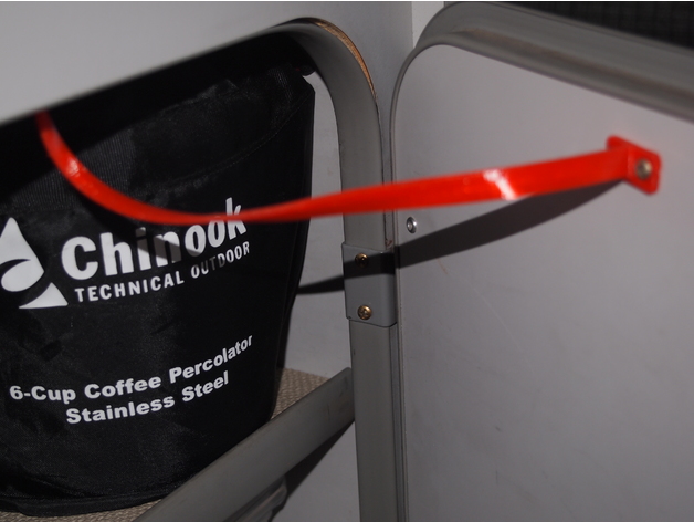
Replacement Door Stopper for VW Vanagon T3 Westfalia 3D Print Model
Summary
Just a replacement door stopper for a Vanagon T3. Print it in flexible filament.
Included is the STL file and 123D Design file. -
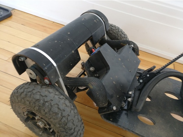
Electric Mountainboard – Enclosure for Enertion FOCBOX / Trampa deck. 3D Print Model
Summary
Enclosure for 2 Enertion FOCBOX Vesc / Trampa deck.
Printed in Advanced PLA / 50% infill.
Check the complete tutorial here: http://makertuts.com/electric-mountainboard-tutorial/ and check my designs for other parts (pulley, ESC/VESC Enclosures…)
Please help me develop new parts and release them for free or just pay me a beer on http://paypal.me/supportp3x to say Hello and/or Thank you! -
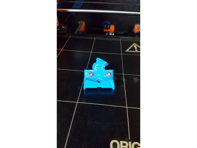
Double 45 Prusa MK2/S heatbed cable cover for enclosures (The Viper) 3D Print Model
Summary
This is a heatbed cable cover for Original Prusa i3 MK2/S designed to work in IKEA lack enclosures. I really liked Neeper’s design and wanted to modify it just abit to better work in my enclosure. I also wanted to lose the zip-tie so I made a little cover for the back held together by two M3x12 bolts and 2 hex nuts. I modified the eyes to have more depth since printing my own so please let me know if you print this and have trouble getting it to fit. -
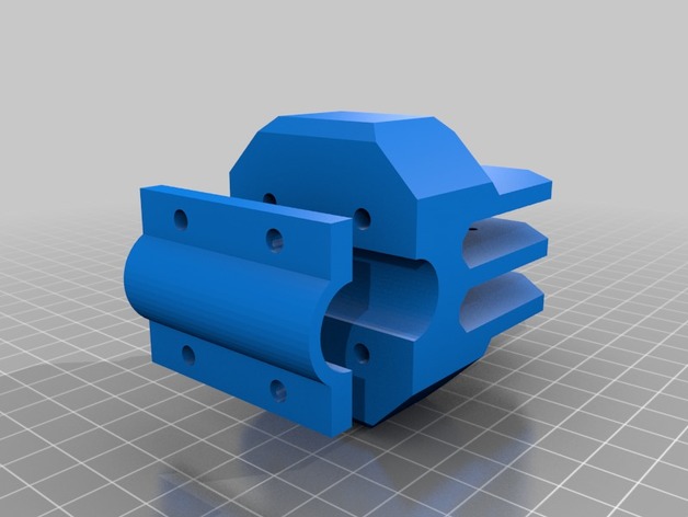
Simple Core XY Componenets 3D Print Model
Summary
Designed for use with my existing design tool head parts below:-
https://www.thingiverse.com/thing:2576080
Z Axis components are below:-
https://www.thingiverse.com/thing:2861738
This design recycles part from large format i3 design.
Please download, use, like & comment.
Some parts (motor mounts) need to be mirrored in your slicer, other are symmetrical so printed as is.
Designed for use with LM8UU bearings and 8mm ground steel rods, Nema 17 motors.
Idlers are of the 12mm, 3mm bore type on amazon / BangGood.
Transport XY, and idler designed to have M3 bolts tread into the plastic without nuts / inserts as there is no load in the shaft direction. -
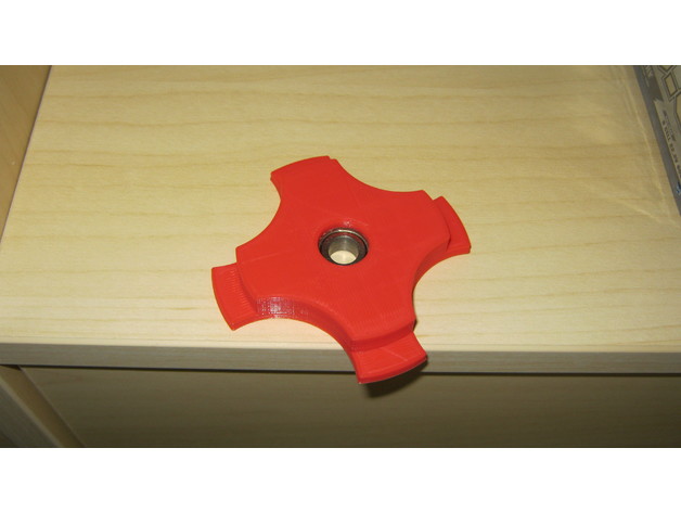
Filament Holder 56mm with Bearing 608Z 3D Print Model
Summary
Filament Holder for 56mm Hole with 605Z Bearing
Layer high 0,2mm
Print Settings
Printer:
CR10S
Rafts:
No
Supports:
Yes
Infill:
15% -
MasterSpool Filament 608ZZ/Roller – Extended 3D Print Model
Summary
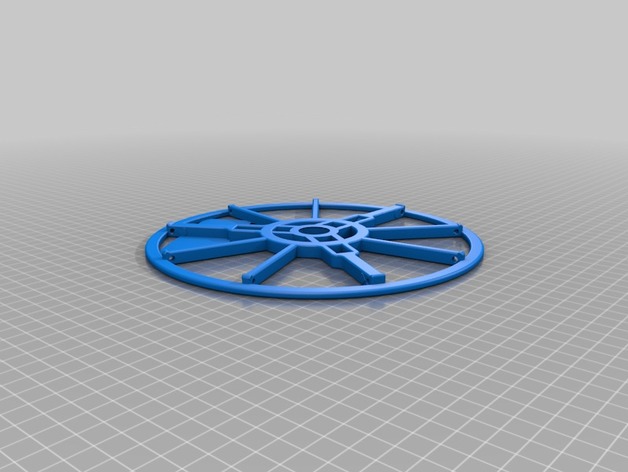
Remix of https://www.thingiverse.com/thing:2835600 – adds additional support arms to increase rigidity. It’s also very slightly taller. I also reduced the size of the hole for the 608zz bearing as I found the original wasn’t quite tight enough. Note that when printed with PLA, I had to gently hammer the bearings in with a rubber mallet.
These are 206mm diameter.
Print Settings
Printer Brand:
Prusa
Printer:
i3 MK2S
Supports:
No
Resolution:
0.2
Infill:
10-15% -
9 Character Smash Brothers Amiibo Plinth 3D Print Model
Summary
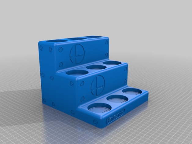
This is a massive print!
First layer is 24mm high.
Second layer is 88mm high.
Third layer is 152mm high.
Amiibo holes are set to 49.5mm as this fits most amiibos well enough with a few being snug.
This print will take a few days to do correctly. This is a warning.
NOTE: I will post my first successful print. I have no concerns about it printing but it is almost 3 days with the settings I will be trying.
I willl use supports to keep the Smash logos looking good.
I also added a little “bolt” look a la Super Mario Bros 3. This led to the rounded look.
I liked the classic Nintendo logo so I used that for the front.
All face extrusions outside of the amiibo holes themselves are .8mm.
How I Designed This
Inspiration
I have many Amiibos and wanted a nice way to display them. One idea was to make an opening Nintendo but that is beyond my skillset and I don’t see a presentable way to make it work. That said, this was simple enough (hardest was getting the Smash Bros vectors right after import.)
Ultimately I went for a soft look to emulate Mario Brothers 3, with “bolts”.
The 64mm per tier is a way to have each amiibo have their own space without getting too into other spaces. .
MOST amiibos should have room here and it will use the majority of a 200mm bed so I did have to “cut some corners” so to speak and the outsides have less room than I’d normally like. -
Feet for a 120mm fan 3D Print Model
Summary
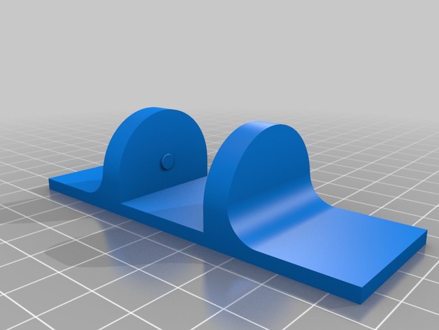
Just like my other set of feet, but these are bigger feets for a bigger fan. All the better to blow you more. 😛
Print Settings
Printer Brand:
Creality
Printer:
CR-10S
Rafts:
No
Supports:
No
Resolution:
1.5
Infill:
20% -
Ikea Lack Slot Grommet 3D Print Model
Summary
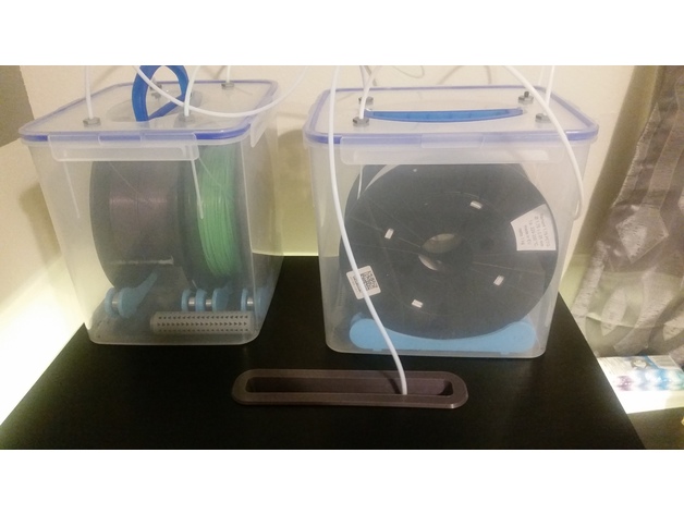
I made this slot grommet to go with my Ikea Lack table setup for my Prusa i3 mk2.5
Two things make this different than other grommets I looked at.it is a slot and long enough that when my printer is doing a tall job that my filament isn’t bending at crazy angles.
The slot is big enough to allow my ptfe tubing to go through it without binding or sticking.
-
RC Airplane Hanger 3D Print Model
Summary
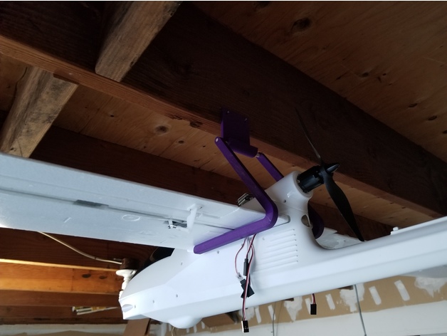
I designed this hanger to mount my RC planes from the ceiling of my garage so that they are horizontal and not vertical. The large version is fit for planes with wingspans of around 1.5m to 2m. I’ll make a smaller version soon to fit planes with wingspans of around 500mm to 800mm.
To make this, you will need 2 of the hooks, one base, two screws or nails, and some 1/4″ wooden dowel. The hooks stay on the dowel with just a press fit, or you can glue them for extra security. Use the screws or nails to hang the base from a roof beam then hang the hooks on the base.
I’m planning on making a base for hanging from the roof of a room inside the house as well.
I designed this using Creo Parametric 3.0.
Print Settings
Printer Brand:
Wanhao
Printer:
Wanhao Duplicator i3 V2
Rafts:
No
Supports:
Yes
Notes:
The base needs supports everywhere to hold the curved over piece. No supports needed for the hooks. -
Xbox One Controller Stand 3D Print Model
Summary
There are a great many holders out there, so why make one more?
I wanted to experiment to see if I could make one I liked a little better.
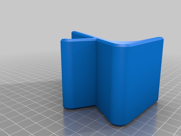
This particular holder fits the controller nearly perfect.
The back is exactly matched for the flat area on the back of the controller. Yes, it will work with Elites!
The height is just perfect to cover the whole of the controller with a little lip peaking out (this is just for general appearance.)
The controller hands down with a hang that is my general taste.
It has a 60 degree slant, enough to give the controller a pivot and keep it well placed.
The “lip” comfortable grips and holds the controller in place (I am surprised at how well and this has been a feature people I’ve shown found somewhat satisfying!)
And finally, it is 6mm thick which really gives it a body that is nice but not chunky. A happy medium.
I actually now use this for a “base” for controller holders. I have made an “Overwatch” version where I have a translucent Orange on a Grey back ground that is friction fit and it looks nice enough (not nice enough to post but definitely hope it gives others ideas.)
If you print one, please leave a comment on what you like, didn’t like, and if you have any functional suggestions (but please make sure to have actually printed one so I can utilize functional data.)
NOTE: There are only a handful of things I would do to make this better.
Produce a “magnetic” version with magnets in the base to stick to metal surfaces/plates.
Place rubber feet on this (I am actually doing this one for a few I’m making for friends.)
Integrate my design into a headphone holder which will likely be a future endeavor. (I just need to get the “screw” process down in Fusion 360, as easy as it is supposed to be.) -
Multi-Purpose Rod Wall Mount 3D Print Model
Summary
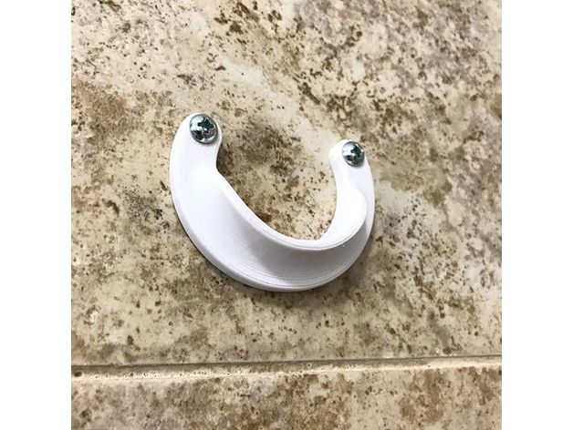
A simple wall mount for various types of rods, such as curtain rods or closet hanger rods. Designed with both aesthetics and strength in mind, it’s also a fairly quick print.
Inner diameter is 40mm. -
BESTWAY pool – main valve – nut 3D Print Model
Summary
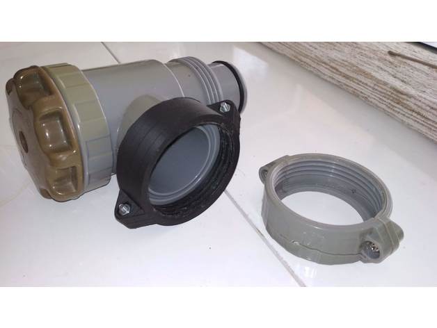
Besway valve and pipe nuts like to break.
I had to earn some extra money, the pool is Steel pro frame – valves that can not be bought.
For assembly needed additionally:
M3 nut – 2 items
M3 screw – 2 pieces
3.5 mm washer – 2 pieces
Print Settings
Printer Brand:
TEVO
Printer:
Tarantula
Rafts:
Yes
Supports:
Doesn’t Matter
Resolution:
0.2 mm
Infill:
100%
Notes:
ABS
bed 90 deg. C
nozzle 245 deg. C
speed 30 – 60 mm/s -
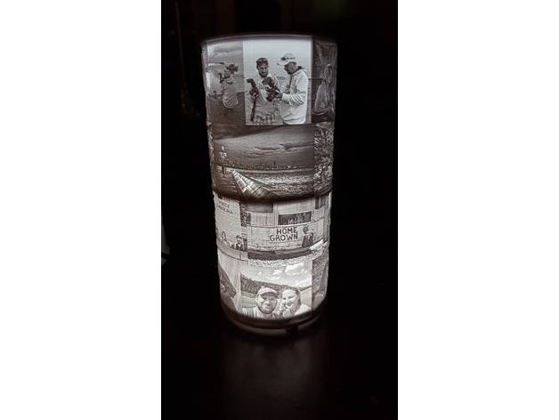
Modular Lithophane Lamp 3D Print Model
Summary
I wanted to find a more cost effective lamp after designing the bluetooth lithophane lamp. Every part of this is printable, all you have to buy is a USB LED and cable. I will drop a link and the end of the summary.
Simply print these parts (and 3 or more of the feet… I use 4), only print the coupler if you plan on stacking multiple lithophanes. Then print a lithophane the same size as the one in my bluetooth speaker thing. 254mm along the longest axis, make it 360 degrees. Height doesn’t matter and however you arrange your pictures doesn’t matter. Then put your parts together. Only glue on your pegs on the bottom and the base connector to the base (after running the USB cable through the hole), then use some thick double sided tape to tape in the LED. You may want to heat-shield the base since the LED gets hot over time and I don’t want anyone catching on fire… either that or limit the time you have the light plugged in (I had mine run for over an hour… it did warp the base slightly in the very center but that was all). I use PLA+ now, the stuff by esun is very good quality white PLA+. I like how it is more black and white than some of the cheaper filament (they tend to have a yellow hue).
I made this modular so that you can print as many lithophanes to go on it as you want… and even stack them (that is the purpose of the coupler) and you can easily swap them around and stack them a few high. I’ve only done two high but the light should be bright enough to go five high or more. It can also double as a flashlight, haha. I’ve powered mine from a USB juice box and taken it on trips to show off as well.
Here is the keychain LED (I soldered mine onto an old USB cable, just solder on the red and black leads). Brand: INVESCH, Part Number: 4328427682… you get 10 for $8, so that’s great. https://www.amazon.com/gp/product/B01H36HLAK/ref=oh_aui_detailpage_o06_s00?ie=UTF8&psc=1
If you solder, any old USB cable will work, just cut the end (the opposite end of the one that plugs into a power supply) and solder the red and black leads. If you don’t solder, then you can get a USB extender and simply plug this USB LED into it. After I solder it I use some heat-shrink to make it look good. I included a picture of the LED soldered on. That is just an example, make sure to use electrical tape, liquid tape or heat-shrink.
Please enjoy and send pictures of any of the thingies that you print out! I’d love to see someone else use some of my designs. -
Tubenquetscher fuer Tomatenmark 3D Print Model
Summary
Tubenquetscher zum Leeren von Tomatenmarktuben. -
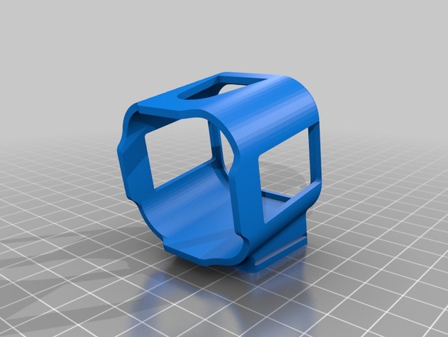
Armattan Rooster/Chameleon Ti GoPro Session Mount 25° 3D Print Model
Summary
25° Session Mount. I haven’t tested it yet it but it should work -
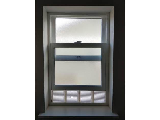
Modular mini-window holder w/ blinds 3D Print Model
Summary
Are you looking for a modicum of privacy in your bathroom or office while keeping the breeze flowing, all without paying for highly customized blinds? Well, look no more (except at an angle)… your modular window-holder-upper blinds are here.
These panels fit together well, with enough space to slightly alter their angle, yet fit flat enough to glue (or not) anytime. These panels are 133mm length (in order for my 533mm windowsill to have an equal 4 across) by 140mm tall, by 15mm depth (fits into the slot under the window).
You can certainly shorten or expand the length as you need. (I’ll create a customizer if there are requests, otherwise any tool should allow this).
The ‘pyramids’ at the top of the print is my (successful) attempt to avoid supports. Only supports printed are at the very bottom cylinder opening.
Note: Your view may vary.
Print Settings
Printer Brand:
Printrbot
Printer:
Printrbot Simple Metal
Rafts:
No
Supports:
Yes
Resolution:
0.3
Infill:
15%
Notes:
I printed at 10% infill, and it works, but I’d recommend 15%. I also did 8000mm/min speed, which slightly shows every-other-layer back and forth issues. 6k would probably work better. Even at 8k/10%, 4 of these took ~10 hours to print and 1/3rd of a 1kg spool. -
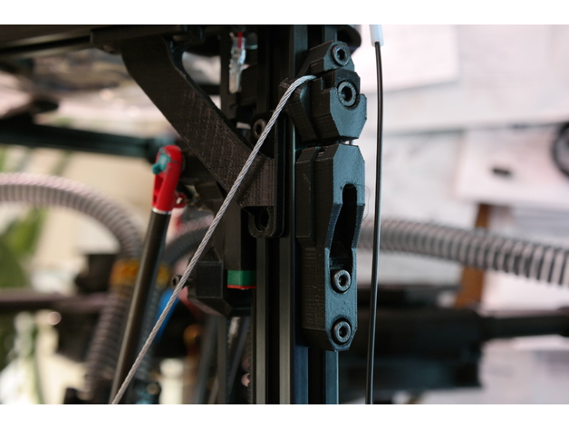
Kossel Wire Cable Frame Braces 2020 (Unlock WARP SPEED) 3D Print Model
Summary
Turn your Kossel from a wobbly tower that rings like a bell into a rigid, no-nonsense, crisp-printing etc. etc. etc. thing of awesomeness with these snazzy-looking anchors for steel wire frame braces and increase either your quality or speed/acceleration by a lot (or meet in the middle someplace), hurray!
It’s basically the same benefit you’d get from screwing big, thick panels of something stiff to all three sides of your printer. Or close, anyway, and waaaaaay less involved.
IMPORTANT DISCLAIMERS: this mod is fairly quick to print, remarkably easy to mount, has a dead cheap BOM, and offers huge and instant benefits, but it comes with the tradeoffs of a moderately reduced build envelope (basically, it’s going to cut off three outside chunks of the build platform somewhere near the inward extent of the horizontal frame members, but exactly how much depends on how far out the build plate extends over the frame horizontals, as well as your arm spacing — on my machine it’s about a 25 mm cut at the deepest) and the need to really verify your bowden/wiring clearances and look for new potential sources of wear — plus you could theoretically destroy your frame corners if you don’t take your time tensioning the setup evenly, although this mod is specifically designed to make it very difficult to apply uneven tension that would wrack your frame to death. Also, I would not recommend doing this mod without also having some compatible corner braces, like mine (https://www.thingiverse.com/thing:2474583), that will transfer twisting moments on the uprights into the horizontals, because otherwise I think this mod could eventually cam the uprights enough to split your corners.
But hey, you’re a big girl/boy and you want WARP SPEED, right? Read on to the design section and I’ll share a semi-secret that’s holding you back if you’ve never monkeyed with the stock Anycubic firmware settings, too!
Anywise. Also see the design section for all my reasoning that led to this design.
You’ll need 3 each of the adjustable and fixed anchors, 3 of the screw adjust mounts, 6 clamp washers, and 1 double eye join, plus:
1/16″ steel cable (about 4.5 meters for an AnyCubic Kossel XL, or estimate by taking your frame’s top to bottom diagonal measurement times 6 + 10%).
3x M5x20 bolts (socket head)
6x M5x12 bolts (socket head)
9x M5 nuts
15x M4x12 bolts (socket head)
15x M4 nuts
4x wire clips (preferably the screw-on kind, not the permanent ones) to fit the wire
Drinking straws in your favorite color
Kapton tape or similar
Special tools:
Wire clippers
A ball-end hex key to fit your M5 bolts will make life much easier.
After I put this on my printer I couldn’t resist dialing up the speed and acceleration to stupid speeds and trying to print a Benchy, and I was pretty shocked when something came out in half an hour that actually LOOKED like a benchy. Is it great? Heck no! My long ol’ bowden and direct drive extruder can’t even approach keeping up with these kinds of speeds. On the other hand, the visible ringing artifacts wouldn’t have been out of place on this machine at half the speed, if that, before I put this mod on it. So at the end of the day it is a vast improvement, but like with most such mods you push out one limitation and put the pedal down only to find the next limitation waiting 🙂 In the case of my AnyCubic Kossel, it’s definitely the extruder followed by the risk of the steppers skipping when doing psycho travel moves near the outside of the build envelope.
Print Settings
Printer:
Anycubic Linear Kossel XL
Rafts:
No
Supports:
Yes
Resolution:
.2 for the anchor pieces, .1 for the washers and eye join
Infill:
95% for the anchor pieces, 100% for the washers and eye join
Notes:
I printed in PLA with 3 perimeters + Cura’s alternating bonus perimeter, 6 top/bottom layers, and ironing on the anchor pieces. I also used Cura’s tree support for the screw adjust anchors to make sure the small lips on either side of the nut socket (gross) didn’t droop. The eye join doesn’t technically need much for support at 0.1 layers, but fiddling with tower/tree settings to get some bonus material around it will make it more likely to print successfully without getting knocked over or warping a lot.
Post-Printing
Super tip: fitting M4 nuts into vertical 2020 slots and holding them in place with something so you can screw bolts into them is a pain in the butt — UNLESS you stick a little rolled-up piece of scotch tape (sticky side out) into the slot first, and stick the nuts to that.
If you have corner braces on your machine, start by loosening up the bolts fixing them to the frame horizontals (you can leave the vertical-side bolts alone; this just ensures that if your frame wasn’t perfectly trued up because of the corner braces, you won’t be fighting that imperfection when you set up the wire braces).
Terminology notes: the fixed anchors are the ones with TWO holes for M4x12s, while the adjustable anchors have ONE hole for an M4x12, and the screw adjust mounts are the guys with the big slot for the M5x20’s. The M5x20 bolts are the ones you’ll use for applying final tension later.
Assembly Steps:
Stick all 9 M5 nuts in all the sockets that need them.
Stuff an M5x20 into each of the screw adjust mounts’ slots and wind it all the way up, then back it off until the one of the adjustable anchors can fit on top of it with no space in the joint. See the pictures if you’re not clear on this.
Bolt the 3 fixed anchors with the wire slot DOWN to the Kossel’s three uprights. Mount these as far down as they’ll go. (NOTE: you could slide them up a little bit — or a lot bit — to gain back some of your build envelope, but the higher they are, the more strain they’ll probably put on your plastic corner pieces. The goal is to have the twisting/tilting loads transferred as directly as possible into compression forces on the frame horizontals, and the further up the anchors sit, the more of a moment you’re inflicting on the corners to transfer the force).
Mount the 3 adjustable anchors at the top of each frame upright with the wire slots UP, and place them about 15-20mm down from the bottom of the plastic frame corner. You’ll need the extra travel above these for the final tensioning later. Don’t tighten these on too much.
Mount the 3 screw adjust mounts at the top of each frame upright with the M5x20 bolts inserted into the holes in the bottom of the adjustable anchors and scoot them all the way up so their top sides butt against the anchors’ bottoms (again, see the pictures…), then tighten them down. Make sure the M5x20’s are snug against the adjustable anchors, but not actually pushing them up yet.
The fun part: string the wire! Well, first put one end of the wire in the eye join and fix it good with two of the wire clips (leave yourself a tail of at least 5-8 cm); then wind the wire twice around the machine through the wire slots in each anchor, alternating up and down, until you get back to the eye join.
Run the second end of the wire through the eye join, snug it up, and tighten on two wire clips just enough to hold the wire in place. Clip off the excess wire, again leaving yourself a tail of at least 5-8 cm.
Now it’s the really fun part: applying the tension!
FIRST, give the top of your frame a rock and a twist to see how much it can flex, just so you have a point of reference when you rigid it up.
NOTE that this design uses a single loop of wire strung all the way around the machine so that you can avoid all the hassle of trying to get six different pieces of wire the exact same length and tension — as long as you don’t lock down the clamp washers until the very end, and make your tension adjustments in small increments to each joint in turn, you should get perfectly even tension all the way around. You can test for even tensioning as you go by simply plucking the wires — if they all generate the same tone, you know you’re good.
We kick off this process by getting as much slack out of the wire as possible by hand, without using the screw adjusters. Do this first by just going around the machine, snugging up each length of wire, and working the slack around to the side with the eye join, then tugging the slack through the eye join and wire clips to hold it in place. IMPORTANT: make sure you get the eye join someplace where you’ll have enough room for both tails, but also where it won’t risk interfering with the printer’s arms. I chose to mount mine pretty close to the top of its side, since the arms can only bump the wires on the bottom halves. This is very much most convenient to get situated while you’ve still got slack.
Once you’ve got most of the slack out, you can go ahead and mount all the clamp washers with the M5x12s. DON’T tighten these on, just get them on enough to put a tiny bit of friction on the wire.
Okay, now you can GENTLY tighten ONE of the clamps for the side with the eye join. This will hold that corner in place so we can work out slack around the machine and back to the eye join to take it out.
Start working around the machine again, taking out slack (easiest way to do this is to pull the wires gently OUT or IN, one segment at a time, in order) from the fixed corner and back to the other side of the eye join, where you can work it out through the eye and wire clips.
Don’t go crazy with the wire, just get it so it’s not sloppy. Now is a good time to do an initial check of how your build envelope is going to change by checking where the arms will touch the wires around the outside of the volume, and to make sure that your bowden and wiring have freedom of movement throughout the printable area. I ended up routing both through the bottom/center quarter of the same side of the printer, but had to shift my extruder a bit to get the bowden moving freely. Be especially sure that the wire and bowden can’t get caught with a loop on the wrong side of the wires in the case of a homing move starting close to that side of the build plate.
When you’ve got the slack pretty well out, tighten down all the wire clips really well on both sides of the eye join.
Now loosen that one clamp back up, along with the bolts holding on the adjustable anchors.
GENTLY screw in the M5x20’s in the screw adjust mounts until they all have about the same tension on them.
Now start going around the machine, CAREFULLY tightening each M5x20 bolt by 1/4 to 1/2 turn each time. The tension will rise faster than you think. GENTLY rock/twist the top of the machine from time to time — this will let you track how the rigidity is coming along, plus it will help distribute the tension evenly by helping the wires scoot around the corners if they need to.
When the frame feels decently solid and the wires feel decently and EVENLY taut (they should make a clear bass note when plucked, and all play about the same note), go ahead and re-tighten the M4’s on the adjustable anchors to fix them firmly to the frame.
This is also a good time to go around and make sure all the other M4’s are good and tight, and to re-tighten the bolts on the frame corner braces that you loosened earlier.
FINALLY! Go around the anchors in order and gently tighten each of the M5x12s to tighten up the clamps. This will put a final lick of tension on the assembly.
Okay, last steps:
You’ll want something on the wires to prevent wear and tear in the event that printer parts do contact the wires. I used scissors at an angle to spiral-cut some plastic drinking straws, which made pretty good ad hoc fenders when wound onto the wires and taped together at the crossing. The bottom halves are crucial to shield against arm contact, along with anywhere your bowden, wiring, etc. might brush up against.
Test carefully at first! A gentle bump or slide of the arms against the wires won’t hurt (the wires will give outward a bit even under a lot of tension), but a hard crash into them could seriously strain your frame. Likewise pay close attention to your bowden and wires until you’re confident they’re not going to bind anywhere. I assume no liability if you bork up your machine with this.
Re-level your printer after this mod (duh).
There’s going to be a wear-in period where some tension is lost to the wires conforming better to the corner radii, the PLA deforming a bit, etc. After a few prints, start by re-tightening all the M4’s holding the anchors to the frame, then loosen all six corner clamps again, along with the adjustable anchors’ M4s, and go around in order again, tightening the M5x20’s by a quarter turn at a time, until you’re back where you want to be, then tighten the adjustable anchors’ M4s again, followed by all the clamps. This might need to happen a few times.
Probably also get some loctite on the wire clips’ nuts.How I Designed This
I genuinely don’t know why nobody’s thought of this one yet (or if they have, I couldn’t find jack about it on Google).
The problem: if you’ve got a Kossel, you know it’s not a rigid setup. You’ve got plastic corners (or possibly metal) to keep the uprights true, but they don’t have much leverage, whereas the forces inflicted on the uprights are pushing way up high, where they have tons of leverage. Take the top frame and push it or twist it and watch what happens to your effector head — it’s going to shift all over the place. It’s not a good recipe if you want to go fast, because going fast takes high acceleration rates, which means you’re pushing your frame harder, which means every start, stop, and corner is like hitting your frame with a bat.
I figured this out pretty quick when I got my Kossel, and my first fix was designing some bolt-on corner reinforcements. They definitely helped with the ringing that came from the stock frame’s lack of rigidity, but they only reduced it, and the reason is pretty obvious from an engineering perspective: they just don’t have good mechanical advantage compared to the forces they’re meant to counteract. I got especially worried about this when I took out my steppers to put in some dampers and discovered that two of the three corners had cracked across the motors’ mounting faces. No idea when that happened, but heaven knows I’d been pushing my printer hard.
Anyway, from the inadequate corner braces, the next logical step is to look at stiffening up each side of the frame with longer braces, and the best-case for this would be braces that go all the way from corner to corner. Rigid braces would be ideal, but difficult in practice — you’ve got to get the lengths and mounting angles perfect to avoid wracking the frame out of true, plus at those lengths you’re not going to be able to count on good resistance to compression forces without having pretty fat chunks of CF tubing or similar, which is going to cost. The other idea (as done on printers like the Fisher) is to mount nice, stiff plates either around the corners or across the sides; I’d regard this as probably the ideal solution, but not the easiest one to implement at home without access to equipment for doing a really precise job of cutting the plates (and/or bending them) and getting all the holes in exactly the right spots. Plus, again, the plates will probably need to be made of something not-cheap even if you don’t have to pay somebody else for the custom fabrication.
So I wondered: why not just go for purely tensile bracing, which would mean nothing more complicated than steel wires? They’d self-align, and if I used a single loop they’d also self-adjust for even tensioning around the structure. Plus, with all the anchors mounted to the uprights, I figured the wires ought to be able to take on a lot of tension without putting terrible strain on the corners. The main tradeoff, then, would be balancing how far to mount the wires from center on the uprights, because too far out would mean giving the anchors a big moment arm to translate the uprights’ deviations from vertical into twisting forces on the uprights themselves (bad for the corners), but too far in would start cutting into the usable print volume by limiting how far side-to-side the printing arms could move. My first design iteration errs well to the “closer to the center” side of this, but if I really start to miss my lost printing volume, I’ll probably start experimenting with how far I can spread the wires without endangering the plastic corners.
Initial testing has shown that these wire braces can improve frame rigidity a LOT for a minor build volume loss; time will tell how it translates into more (or less, hopefully) wear and tear on the rest of the printer from reduced cyclical wear on the frame.
Oh yeah, and that secret to warp speed? Go into your firmware and change your DEFAULT_MAX_FEEDRATE to something like {400, 400, 400, 400} and your DEFAULT_MAX_ACCELERATION to something like {9000,9000,9000,9000}. If you’ve never done this, you’ve probably been stuck all this time with a speed limit of 200mm/s and 3k mm/s^2 on all axes. Even if you don’t push your speeds/accelerations up to these new limits, you might be surprised at the effect of raising them — in my case, I think my extruder had been constrained somehow by the lower limits, because until I made these changes my prints always suffered from underextrusion above about 30mm/s at 0.2 layer height.
But once you’ve raised the limits, it’s worth seeing what a 350mm/s travel move really looks like at 5500 or 6000 mm/s^2. (Answer: sorta scary, honestly)
Designed from scratch in SketchUp. -
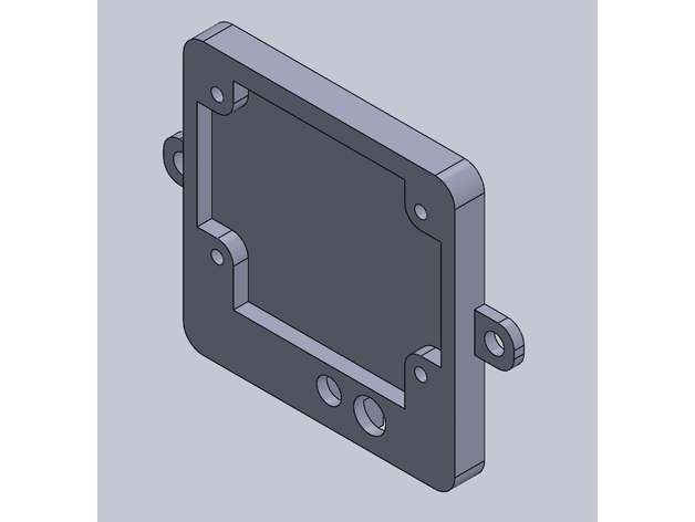
Backplate W1209 Modified for case 3D Print Model
Summary
I Have made this remix for fix using M4 screw, and wood fix. -
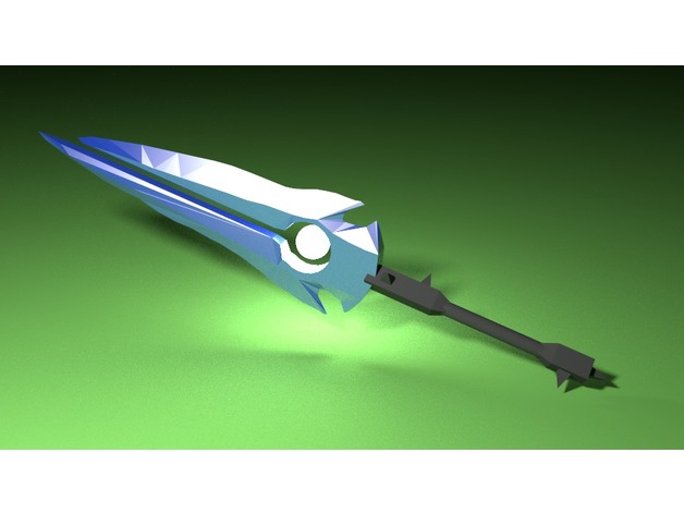
Thunderfury 3D Print Model
Summary
Thunderfury, Blessed Blade of the Windseeker!
For ya’ll old school WoW fans. -
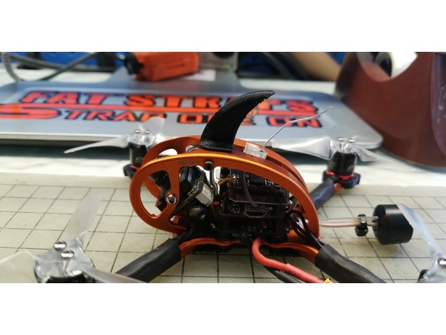
Emax BabyHawk Roll Fin 3D Print Model
Summary
Simple shark fin for the Emax Babyhawk/Babyhawk R. Should slip right on with the standoff within. I printed it laying on its back for sturdiness with supports on the underside.
Print Settings
Printer:
Anet A8
Rafts:
No
Supports:
Yes
Resolution:
0.2
Infill:
N/A -
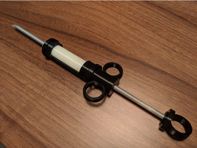
Plague Doctor Syringe 3D Print Model
Summary
What to print:
You need the “Body-Ring” three times. Every other part is only needed once.
How to assemble:Glue 2 of the 3 body-rings onto the “handle-holder” part.
The remaining ring is glued onto the “plunger-cap”Screw the handle-holder and the fluid onto the body. Both go in thread first.
Put the Body-Ring onto the fluid.
Screw the needleside-cap and the needle onto the fluid.
Pull the plungerside-cap over the plunger, thread first.
Screw the plunger into the plunger-cap
Push the plunger-assembly into the syringe and screw it onto the handle-holder.
Et voilà
You could print the Body and Body-Ring as one object, if you used support material.
Print Settings
Printer Brand:
Prusa
Printer:
i3 MK2S
Rafts:
Doesn’t Matter
Supports:
No
Resolution:
0,2mm
Infill:
30-40%
Notes:
You might need to adjust the clearances. I added the Fusion360-project for that. -
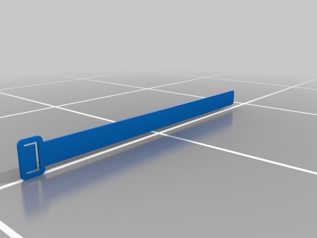
Plant Ziptie 3D Print Model
Summary
you use this to attach your plant to a stick to hold it vertically -
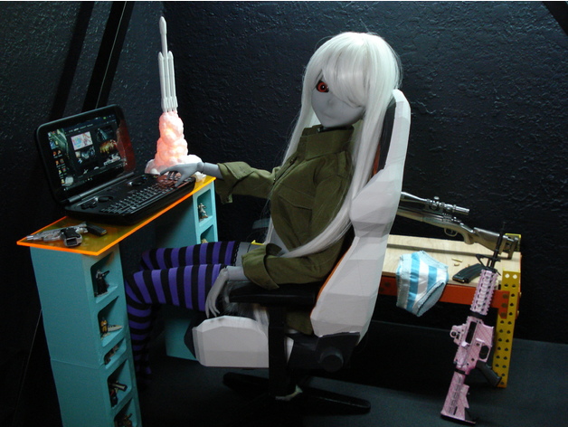
1/3 ball joint doll bjd 3D Print Model
Summary
This project was a lot of fun, and very cheap. This BJD was originally designed by Driftgirlhttps://www.thingiverse.com/driftgirl/about
It was then reuploaded by sarf2k4https://www.thingiverse.com/sarf2k4/about
This version from me rescales the head from sarf2k4 to match the body, and modifies the files slightly. you will need a 9-10″ wig. Mine was $11.98 on eBay. All wigs are slightly different and the one I bought was very tight and almost wouldn’t fit. If you slowly pull the wig on one side at a time it will work. You will also need a 9-10″ wig cap. I prefer silicone, it costs $1.16 on ebay. For the eyes, I found that 22mm works best. My eyes were $12.28 on eBay. You will need eye putty. At least 8 grams for the eyes. Cost is $1.15 on eBay. As you can tell, eBay is a great source for everything related to ball joint dolls. Everything I ordered shipped from Shenzen, China. So depending on where you live it will take a couple of weeks to arrive.
A note on sanding and smoothing.
You will need to sand the doll A LOT. Sanding by hand takes a very long time. instead, make the sanding disk seen in the pictures. just cut a circle in regular sandpaper, poke a hole in the center, and attach it to a rotary tool. You will need to use a very slow speed setting. The sanding disk is flexible, so it can get into hard to reach areas. This will save you a HUGE amount of time.
This is the process I use…
Spray paint everything with Rustoleum filler primer in a thin even coat. Wait 24 hours for the primer to dry as it shrinks while drying. Next, sand everything with 80 grit until the surface is rough but no longer has layer lines. Most of the paint will be removed during this step. Then sand with 120, 220, 300, 400. I cleaned it with isopropyl alcohol, then I sprayed again with Rustoleum filler primer in a thin even coat. Give it 24 hours to dry, then VERY LIGHTLY BY HAND sand with 800 grit sandpaper. This is to remove the rough texture of the Rustoleum filler primer. Then spray with a Krylon matte clearcoat, allow a few hours to dry, and the doll will be super smooth. During painting, suspend the parts with wire as seen in the picture to avoid rough patches. If there are any holes in the pieces, before you start painting and sanding get a tube of Elmer’s carpenter’s wood filler and rub a small amount into the holes with your finger. It shrinks a little when dry, so you may need to do this twice. I had to fill in the back of the hands, and the tops of the shoulders.
A note on color and faceup.
I am not an artist, and proper faceup is VERY difficult. That is why I went with gray skintone, black eyes, and heavy bangs as it allowed me to avoid faceup. If you want a propper faceup, but like me don’t have that ability, I would suggest sending your doll’s head to an etsy artist. They work on commission and produce some excellent work. https://www.etsy.com/market/faceup
A note on stringing.
I used 3mm elastic cords. 10 yards will be much more than you need. I used small nails, and bent them into s hooks for the hands, feet, and head. Use a paperclip to get the shape right, then copy the shape with a nail. I strung in three sections. The hands were connected across the chest. The feet were connected across the groin, and the head was connected to the groin by drilling two holes in the lower stomach where the bumps are. There are lots of ways to string a doll, so look online and decide which way you want to try.
I am happy to answer any questions. Have fun making your doll! -
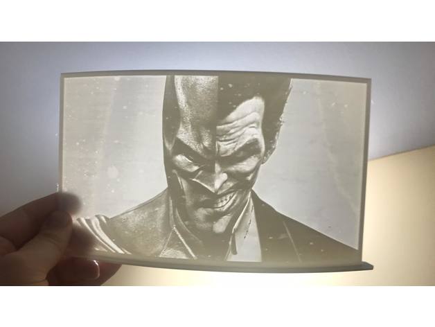
Batman vs joker 3D Print Model
Summary
yet again another lithophane for my friend.
i like this one alot.
Print Settings
Printer Brand:
Creality
Printer:
CR-10S
Rafts:
Yes
Supports:
Doesn’t Matter
Resolution:
.15
Infill:
100 -
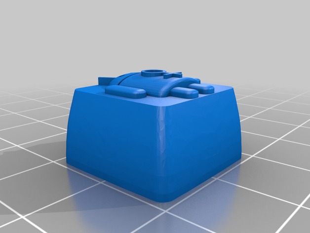
Femdroid Keycap 3D Print Model
Summary
Femdroid Keycap!
Cherry MX Stem, Designed to work with R1 OEM and SA profile.
All parts modeled so that this is printable with 0.4mm nozzles and best results when layer heights are 0.1mm or smaller. -
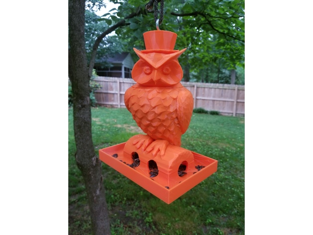
Owl Birdfeeder 3D Print Model
Summary
This is a large birdfeeder, prints without supports. 20% fill worked great. Birds love it. -
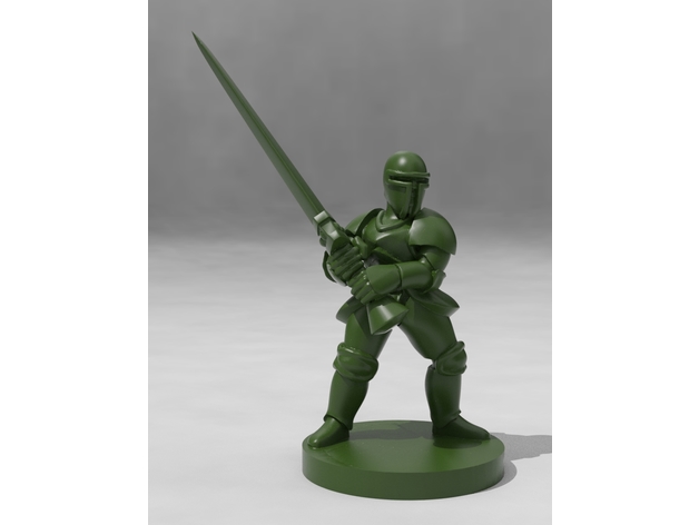
Armored Knight with Greatsword 3D Print Model
Summary
In the late Medieval period, during the early to mid Renaissance, the heavily armored knight was the king of the battlefield. While they rarely wielded massive great wedges of steel like this, he’s certain to at least intimidate any giants or dragons he quests against, seeking to rescue his kingdom’s princess! Little does he know she’s already rescued herself, she’s no shrinking violet… -
Box for keynya’s Nintendo ds / 3ds game card holder 3D Print Model
Summary
Box for keynya’s Nintendo ds / 3ds game card holder
Print Settings
Printer:
Anycubic i3 Mega
Rafts:
No
Supports:
No
Resolution:
0.2 mm
Infill:
20% -
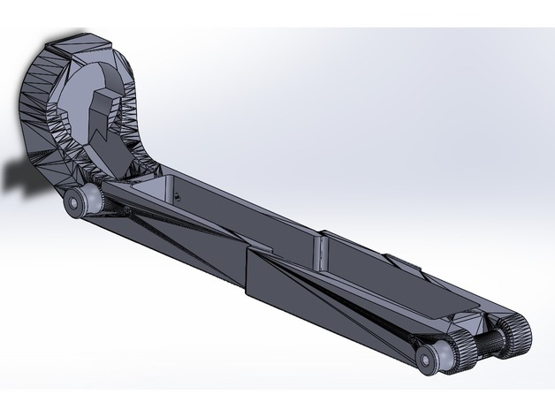
AR-15 Upper Receiver Cover V2 3D Print Model
Summary
Upper receiver cover for the AR15 platform, remixed from ZBROYAR’s cover (https://www.thingiverse.com/thing:2816693). This allows you to store your upper and Bolt Carrier Group together, and prevents dust/dirt/whatever intrusion into your receiver.
This version is optimized for faster printing, lower filament usage, easier assembly, and easier take-down.
Changes:
1) Removed material from center of model
2) Removed material from inside buffer tower
3) Removed text from bottom of model
4) Chamfered front mount area
5) Lengthened take-down pins and contoured to improve grip
Print Settings
Printer:
Qidi X-Pro
Rafts:
No
Supports:
Yes
Notes:
Print with the tower oriented vertically and on top. Supports everwhere.
How I Designed This
SolidWorks FTW!
Full CAD files provided, please feel free to remix to your little heart’s content. -
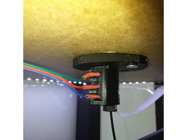
Lack Filament Sensor 3D Print Model
Summary
This is a microswitch filament sensor mount I’ve made for the IKEA Lack enclosure.
It takes 1 KW-12 switch.
Print Settings
Printer Brand:
Prusa
Printer:
i3 MK2S
Resolution:
0.2
Infill:
20
Notes:
Support on build plate only.
The lid snap isn’t perfect at 0.20 layer height. It hasn’t fallen off for me yet but you can try a higher resolution if you like.
Post-PrintingSwitch preparation
The switch lever should be slightly bent to an “S” shape as shown above. The first bend is done to insure the filament engages the switch. The bend at the tip is done to prevent the metal lever from snagging on the filament when you pull it back to the spool.
If you solder the leads you should do it before you insert the switch to the housing. The housing is also designed to allow open barrel terminals but I haven’t tried it yet.
The switch only goes into the housing with the lever pressed against the switch body. It should spring back into place once the switch is seated all the way in. If the lever stays pressed (meaning the switch is engaged and activated) you’ve probably bent the lever a bit too far up. -
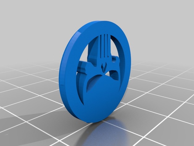
Magura MT4 Ring 3D Print Model
Summary
Brake cover ring for Magura MT4
Print Settings
Printer:
i3 Mega
Rafts:
No
Supports:
No -
Wanhao Duplicator 7 (D7) mask test 3D Print Model
Summary
This is the test files to create digital MASK for Wanhao Duplicator 7. For more info you may follow to http://3dtoday.ru -
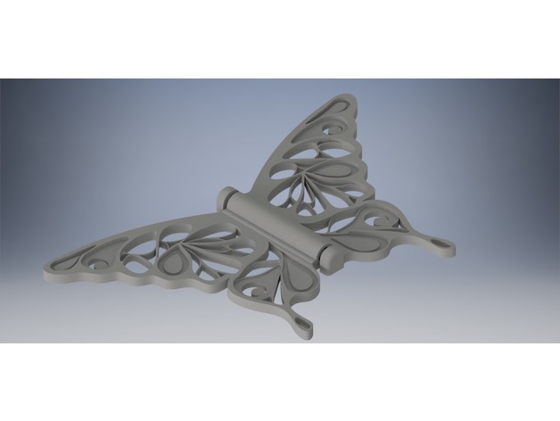
Ornate Hinge Butterfly – Swallowtail 3D Print Model
Summary
This is a re-imagined concept of a hinge butterfly, designed to resemble a swallowtail butterfly. I have included 3 different versions with varying amount of holes. These butterflies make excellent decoration when glued into position.
Print Settings
Printer:
Kodama Trinus
Rafts:
Yes
Supports:
No
Infill:
None
Notes:
Super Simple to Print
How I Designed This
I designed this using Autodesk Inventor, and made a very simple hinge from which the butterfly was created. -
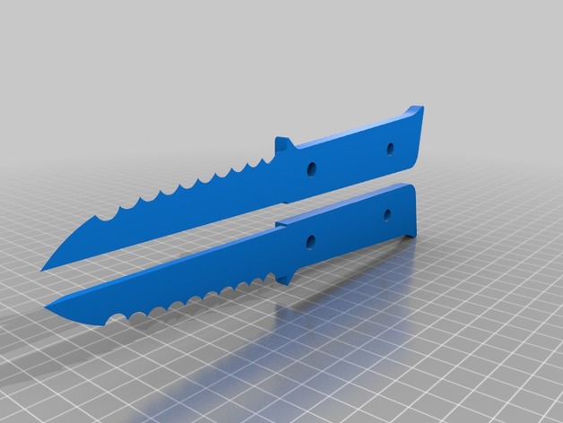
knife 2 3D Print Model
Summary
Do not Run with knives
Not responsible for any injuries.
.1 height, 100%infill on blade,
nice steak knives or around the garden use. -
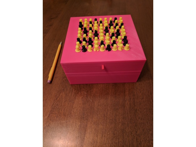
Sudoku Puzzle Box 3D Print Model
Summary
This fully 3d printable box remains locked until the Sudoku puzzle displayed on its top is solved. The puzzle is displayed using knobs pointing to numbers on the box lid. Some knobs are fixed (these are the filled-in numbers on the puzzle) and some are free to rotate. As they rotate, a detent mechanism gives tactile feedback and keeps the pins in place. Once solved, a button on the front of the box is pressed, and the top becomes free to lift off the box. The puzzle is configurable by rearranging different combinations of pins.
Parts:
box.stl – This is the base of the box.
pins-moving.stl – These are all of the rotating pins needed to make any Sudoku puzzle. Included are 81 pins, 9 corresponding to each number. The number each pin corresponds to is printed on its side. Also included are cylindrical supports up the side of the pin. This improves stability, as the pins are tall and have a narrow base.
pins-fixed.stl – This is similar to pins-moving.stl, but contains pins that are fixed in position and cannot move. These are used for the “filled in” numbers of the puzzle.
slideplate.stl – Part of the locking mechanism. The front part of this protrudes as the button (so print it in the desired color for the button).
clips.stl – Internal to the box, these hold the mechanism in place against the lid.
baseplate.stl – The base of the internal mechanisms. It also contains the detent prongs. I recommend printing this in PETG to allow for some flex.
lid.stl – This is the top part of the box. On its face are printed circles of numbers, so ensure your bed is level and Z height is set correctly.
knobs.stl – These knobs press on top of the pins to make them easier to grip. Print 2 sets of these, one in the color for fixed pins, and one in the color for moving pins.Print Settings
Printer Brand:
Prusa
Printer:
i3 MK3
Rafts:
No
Supports:
No
Infill:
20%
Notes:
I used 0.15mm layer height and an 0.4mm nozzle; other settings may work as well.
Post-Printing
Step 1. Detaching Pins
The pins print with included supports and must be removed from them. They can be removed by pushing straight down on the tops of the pins, out through the bottom of the support platform. Remaining strings at attachment points on the pins are not generally a problem.
You may wish to leave pins attached to the support platform until configuring a puzzle to keep them organized (in rows by number).
Step 2. Configuring Puzzle
Place the base plate on a flat surface such that the detent prongs are facing you (see orientation in photo). Place pins onto the base plate such that the cylinders protruding from the base plate fit into the holes in the bottoms of the pins. Fixed pins should be used for preset positions in the puzzle while moving pins should be used for blank positions. Place pins such that the large slot in the side of the pin is facing you; this should also align a small groove on the opposite side with the detent prong.
If there is a bit of stringing on the base plate, this is usually OK. Remove any large chunks, and just push the pin through the rest, breaking the strings.Pins inserted into base plate
Step 3. Assembling the Lid
Turn the lid upside-down (such that the numbers printed on the surface are facing downward). Place the slide plate into the lid, inserting the protruding arm of the slide plate (the button) into the hole in the front of the lid. Gripping the button (now protruding through the lid), pull the slide plate to the front of the lid.
Now flip the lid, continuing to pull on the button. Ensure the slide plate is staying roughly level with the top of the lid. You may have to pull a bit hard to counteract gravity and the leverage of the sliding plate. Pulling out and slightly down (using the button as a lever) can make this easier.
Place the lid and slide plate over the base plate, aligning the front of the lid (with the button protruding) to the front of the base plate. Carefully lower the lid, watching from the side to keep the posts protruding from the underside of the lid aligned with the corresponding cutouts in the base plate. If pin shoulders snag on the slide plate, just wiggle the lid a little to get them through; the shoulders of the pins are tapered to help this. Once the tops of the pins reach the underside of the lid (you can see them through the holes in the lid), wiggle and tap the lid a bit to get the pins to go through. Both the underside of the lid and the tops of the pins are tapered.
After lid has been placed on top of base plate, and pins inserted through the holes in the lid, pick it up, and push the lid all the way down. The cutouts on the base plate should seat firmly on top of the lid posts (see picture).
Take each of the 3 clips, and slide it from the side underneath the clip holders. The edges of the clips are chamfered to help this. Ensure the clips are tilted toward the clip holders when first inserting them to get them started. The 3 half-spheres attached to the bottom of the clips should snap into the corresponding holes in the bottom of the base plate. (see picture)
After finishing the assembly of the lid, flip it over again (so that the printed numbers are facing up). Ensure that all pins are pointed at the correct numbers, then push the button on the front to test the locking mechanism. The button should move in about a centimeter. If there are strings on the slide plate or inside the slots on the pins, it may take additional force the first time the button is pushed to break through the strings.Adding Knobs
Place the lid with the top facing up on a flat surface. (I recommend doing this while the lid is not placed on the box so the force required to push on the knobs does not damage the clips.)
Take each knob and firmly press it down on top of the pin. Ensure the opening in the knob is aligned to the mark on the pin, and to the number indicated by it.
After this, place the lid on the box, aligned to the front (the front of the box is the side with the slot), and assembly is completed.
Locking and Unlocking
To lock the puzzle, pull the button outward, and turn the moving pins to their upward positions (blank). To unlock, turn pins to the correct positions and push button inward. -
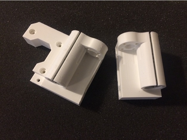
P3Steel X axis for Lead Screws 3D Print Model
Summary
I made this based on the Toolson design for the p3Steel. It will allow the use of a 8mm Lead Screw.
Print Settings
Printer Brand:
Prusa
Rafts:
No
Supports:
No
Resolution:
.2
Infill:
60% -
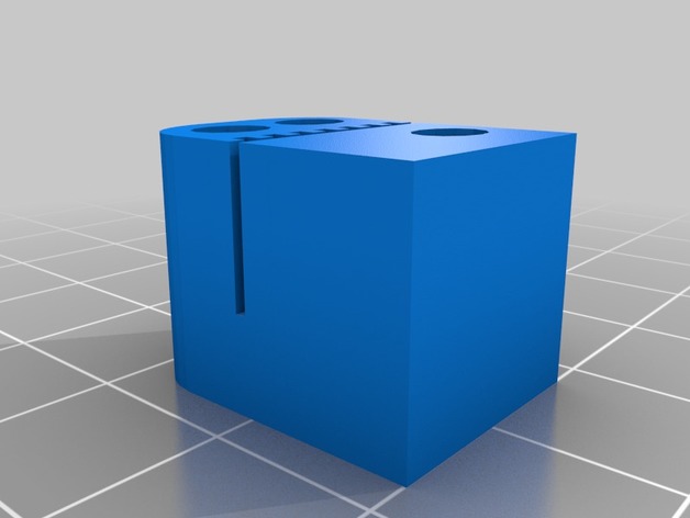
a8 x belt holder.stl 3D Print Model
Summary
A remix of Anet A8 prusa-i3 x-belt holder (6 holes) by Sjouke. I just basically removed the middle part because is thin and I didnt need it, and I made the belt space .2 mm thinner. Mirror the part in your slicer to print the other piece. -
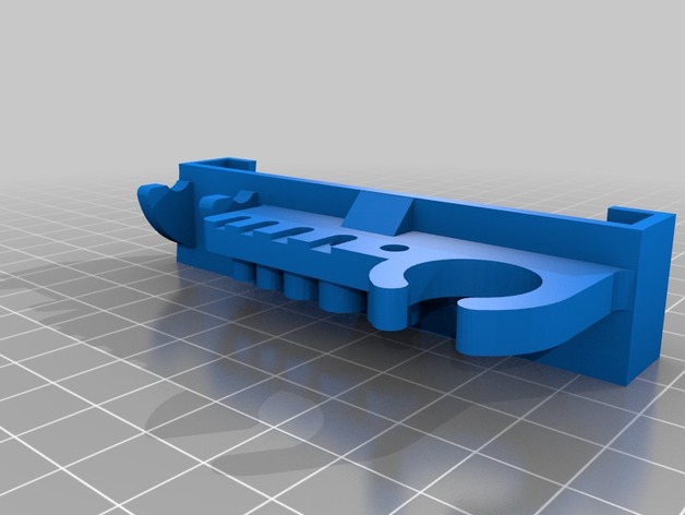
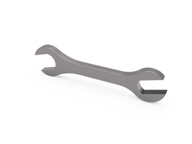
a8 slide on tool holder with wrench 3D Print Model
Summary
A remix of 2 different tool holders, fits every tool that came with the a8 except the wire cutter and doesn’t require screws. -
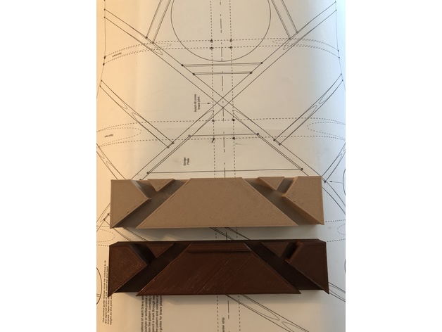
StewMac Dreadnought Bridge Caul 3D Print Model
Summary
This caul is based on the designStewMac gives in their dreadnaught assembly instructions. The caul fits under the soundboard and allows you to clamp the bridge firmly while gluing it to the guitar.
Print Settings
Printer Brand:
Prusa
Printer:
Prusa Clone
Rafts:
No
Supports:
No
Resolution:
0.20
Infill:
20% -
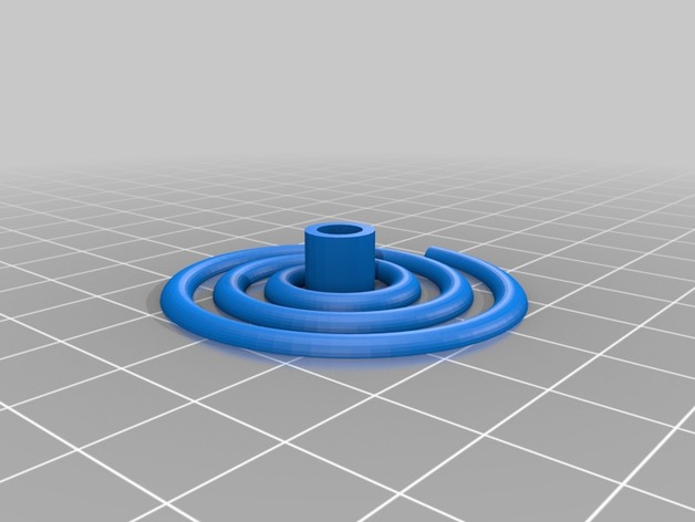
Spiral Stepper Motor Ornament 3D Print Model
Summary
Spiral Stepper Motor Ornament, slides onto an a8 stepper motor. -
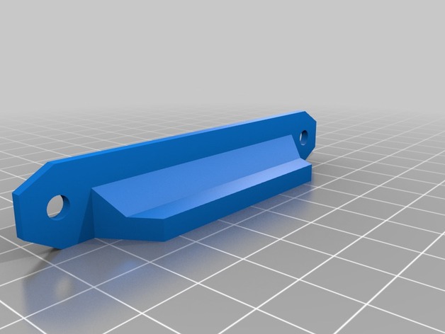
Prusa Lack Enclosure Door Handles for 20mm x 5mm x 2mm Magnets 3D Print Model
Summary
Using the source files from the Prusa Lack enclosure, I resized the magnet inserts for 20mm x 5mm x 2mm magnets, which were easier to find on eBay.
Print Settings
Printer Brand:
Prusa
Printer:
i3 MK3
Rafts:
No
Supports:
Doesn’t Matter
Resolution:
0.15 mm
Infill:
20% -

Maserati Logo Sign 3D Print Model
Summary
This is an Maserati Logo Sign for my garage.
It is printed in:
White to 1.1mm
Blue to 2.1mm
Red to 3.1mm
Print Settings
Printer Brand:
FlashForge
Printer:
Creator Pro -
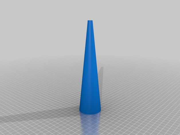
Mandrel for hoop earrings 3D Print Model
Summary
Decided to make some hoop earrings for my girlfriend.. looked up what all tools I would need and decided I didn’t want to spend $40 for a tapered cylinder. I figure this will work for a few sets as I’m not looking to become a professional jeweler. It is 50mm at one end and 10 mm at the other. -
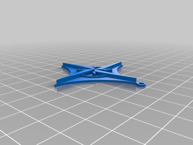
Compass Necklace 3D Print Model
Summary
I designed this necklace for a friend of mine who is a fan of maps and compasses. It’s pretty simple and a quick print. -
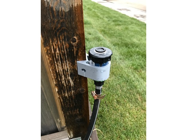
Custom sprinkler holder for irrigation system 3D Print Model
Summary
As with my other things, I working on installing a custom irrigation system.
I needed a sprinkler holder to fit on the corner of my fence.
for reference, the sprinkler used is the following: https://www.homedepot.ca/en/home/p.2-inch-spring-loaded-pop-up-sprinkler-head-for-landscaping.1000117651.html
Have fun and enjoy !
Print Settings
Printer:
QIDI Tech 1
Rafts:
Doesn’t Matter
Supports:
Doesn’t Matter
Resolution:
0.2mm
Infill:
10%
Notes:
Printed with PLA
Temp = 230
Bed = 60
Speed = 90 mm/s -
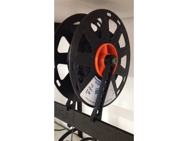
Centrador Nuevo Carrete Printalot 3D Print Model
Summary
Centrador de carretel Printalot para Prusa Original -
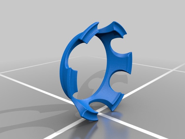
Clever Dripper to Large Tervis adapter 3D Print Model
Summary
Adapter to span needed gap between diameter of 24oz Tervis Tumbler and Clever dripper coffee dripper for those who need a little more coffee in the morning. -

Parametric cup 3D Print Model
Summary
Its a cup! You can set height/width and volume in millilitres.
Have fun! -
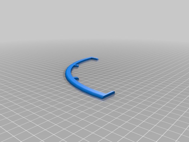
Big Bullzeye Clock – Pieces cut for 200×200 build plate 3D Print Model
Summary
These are pieces that are too big for a 200×200 build plate cut to fit – super glue together -
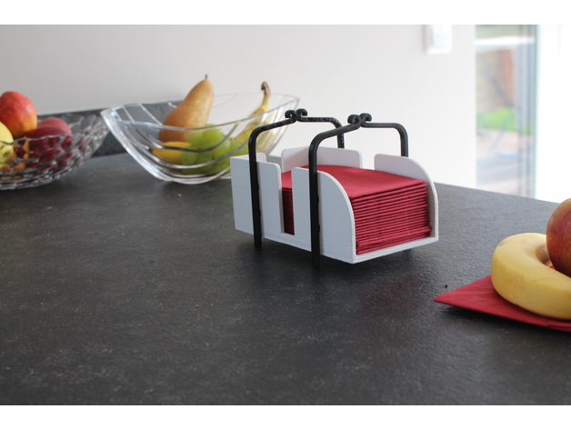
1/8 Napkin holder 3D Print Model
Summary
Englisch:
This is an elegant three-piece Napkin holder that can be printed without Support material.
Deutsch:
Das ist ein eleganter dreiteiliger Serviettenhalter der ohne Stützmaterial gedruckt werden kann.
Die Links zu unseren Seiten:
Unsere Website:(WIP)
Twitter:https://twitter.com/CloneB31
Instagramm:https://www.instagram.com/cloneb31
Pinterest:https://www.pinterest.de/cloneb31
If you like our Designs please Donate us, or Show your love with a tip.
Patreon:https://www.patreon.com/CloneB -
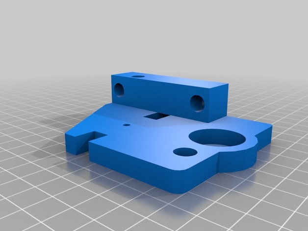
Geeetech i3 Pro B Top Z Bracket with M8 Support. 3D Print Model
Summary
Have some left over M8 all-thread after upgrading to lead screws? This might be the perfect up-cycle option for them
Print Settings
Printer:
Geeetech i3Pro B
Rafts:
Doesn’t Matter
Supports:
No
Resolution:
.2
Infill:
30 -
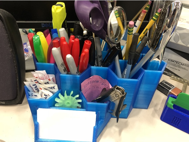
Desk Organizer 2.0 3D Print Model
Summary
This is a remix of https://www.thingiverse.com/thing:1226652. I needed more space and a better/larger card holder. It’s pretty large. May not fit on some printers.
Print Settings
Printer:
Folger Tech FT-5
Rafts:
No
Supports:
No
Resolution:
.25
Infill:
20% -
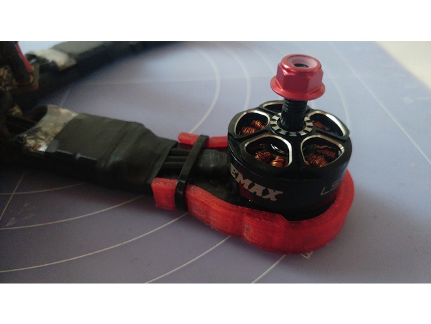
QAV-R TPU arm protector 3D Print Model
Summary
Simple and light arm protector design to be printed in TPU. 100% infill, support optional. -
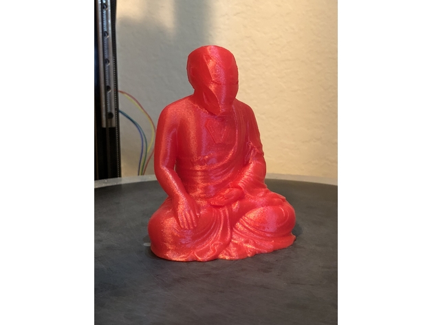
Iron Buddha 3D Print Model
Summary
I made this model from the two sources. I cleaned up the original Vader Buddha mesh, and then had an idea when i was printing off the Mark 50 head… so here’s the iron buddha. It slices fine in S3D (they have the most finicky slicer, imo). Definitely need supports for his chin. I used them on his arm, the hand in his lap, and a little on the back of the head, but i don’t think those ones were necessary there… I printed him in translucent red PETG from Makergeeks.com. It came out with a nice shine/sparkle, and printed very clean.
Print Settings
Printer:
homebrew delta
Rafts:
No
Supports:
Yes
Resolution:
.2mm
Infill:
15% -

ORIGINAL XBOX for PI3 3D Print Model
Summary
working with a buddy, i’m the designer for a case and he’s the programmer for the console.Standards
CCSS
Overview and Background
Lesson Plan and Activity
thanks
Materials Needed
filament -
Kulu-ya-ku Icon 3D Print Model
Summary
I turned the icon art for the Kulu-ya-ku into a 3D object. There’s two versions you can grab; either with a flat back or with some hollowed out areas. Besides it saving some material, I use the hollow areas to put in some magnets so I can easily attach it anywhere I like (as long as it’s metal).
The hollow areas are 1/3 of the total height of the object, so if you also want to add some magnets, measure your magnets to know how high you should print for a perfect fit!
Print Settings
Printer:
Malyan M200
Resolution:
0.175mm
Infill:
20%
Notes:
You only need supports if you use the hollowed version. -
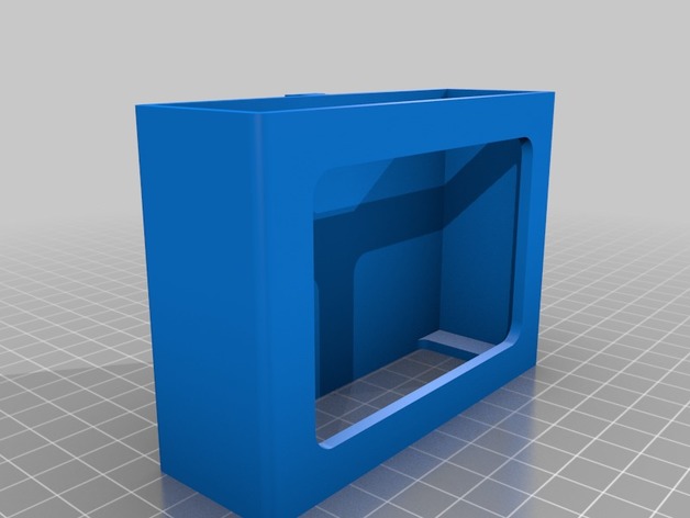
IOGEAR GUS434 USB switch / Ikea SIGNUM chassis 3D Print Model
Summary
Redid the cable management at my desk and didn’t like how my IOGEAR switch was hanging in the air. Built a chassis that attaches to the IKEA SIGNUM cable management rack. -
E-nable porte-clef 3 colors 3D Print Model
Summary
Porte clef E-nable en 3 couleurs , pause M600 pour les changement de couleurs , a faire en séries de 10
Print Settings
Printer Brand:
FlashForge
Printer:
Dreamer
Rafts:
No
Supports:
No
Resolution:
0.15Custom Section
-
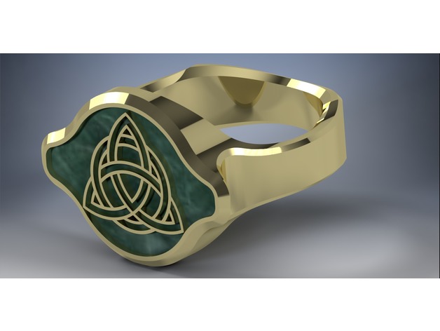
Celtic styled ring 3D Print Model
Summary
Ring designed with a 1 inch inner diameter. scale up or down to match your ring size. The ring face is just a hair below 1in in diameter and the ring band height is 1/4in with a thickness of 3/16in.
The ring features a Celtic knot design that is modeled at 1mm in height and roughly 1/2 mm wide.
The 2nd version of the ring includes a small chamfer around and within the knot design.
I have included the inventor file if anyone is included to alter or improve upon this ring. -
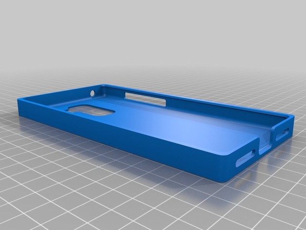
Leeco Le pro 3 case 3D Print Model
Summary
I searched for a le pro 3 case in thingiverse and I find nothing so I just maed this one for all leeco users!
No supports needed! -
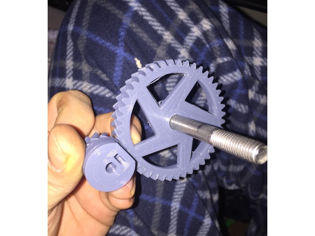
Custom Wade’s Gears for 1.75 (.300 ~titan ratio) 3D Print Model
Summary
Custom Wade’s Gears for 1.75 (.300 ~titan ratio)
The big gear is 10mm, the small is 12mm centered. it runs better and truer… it has a nut trap for a M3, also it does have a D shaft on the small gear. Big gear is for 8mm hobb bolt. -
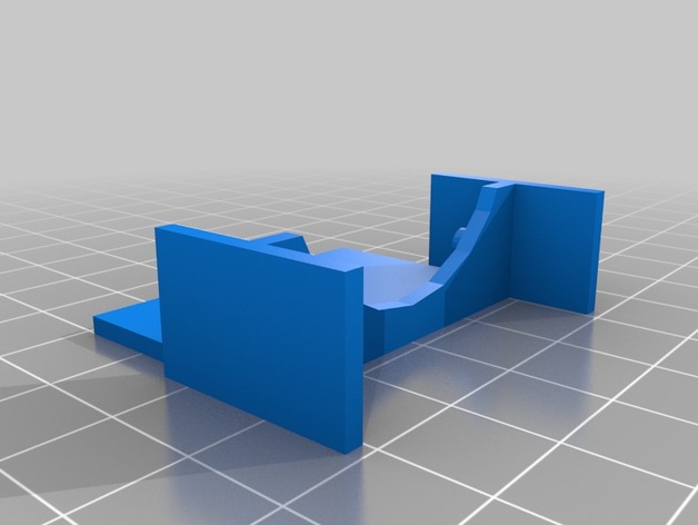
Wanhao/Monoprice i3 Mini Fan Shroud (Mk 2) 3D Print Model
Summary
This product allows i3 Mini users to effectively turn off print cooling and then turn it back on once the initial layer is finished. Without stopping the print or making permanent mods to the machine! This part can drastically improve bed adhesion on the lovable i3 Mini.
The i3 Mini lacks a second fan for cooling the printed filament. Instead it has a baffle that splits the airflow from a single fan onto the build bed as well as the hotend. This design choice likely helps to keep the i3 Mini inexpensive, but also creates a major flaw in that there is no control over print cooling as the one fan must remain on at all times to control the hotend temperature.
I found that the i3 Mini therefore required a fair amount of work to get decent bed adhesion. Blue tape, glue, slow speeds, etc were all necessary to get a usable initial layer. Unless the airflow is blocked from reaching the build plate. So I created this fan shroud which slides on and off easily; allowing the user to effectively turn off the fan for the first couple layers (or the entire build if so desired). Once a solid layer is complete and print cooling is needed, the user only needs to gently tug the shroud off and the rest of the build goes as expected without interruption.
Print Settings
Printer Brand:
Wanhao
Printer:
i3 Mini
Rafts:
No
Supports:
Yes
Resolution:
0.4mmW x 0.2mmH x 60mm/s
Infill:
Parallel Lines, 20% -
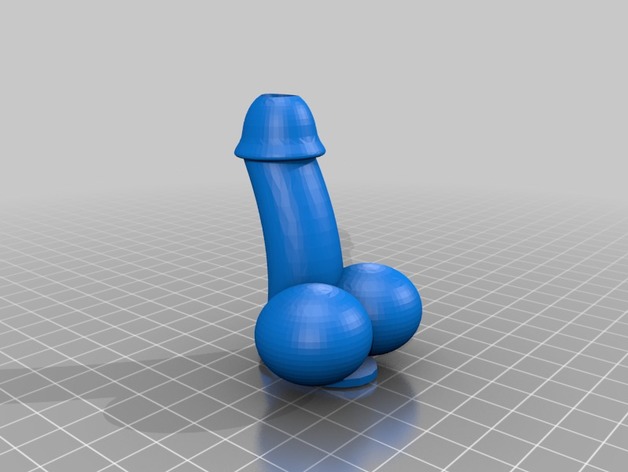
Penis Vase 3D Print Model
Summary
Slightly modified nikolam’s “Penis Drip Tip” from a vape accessory into a phallic plant vase. Not perfect, but works well. Great gag gift!
Print Settings
Printer Brand:
XYZprinting
Printer:
da Vinci miniMaker
Rafts:
No
Supports:
No
Infill:
20%
Notes:
Penis vase -
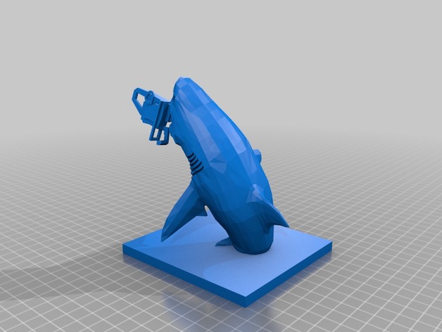
Sharknado!! 3D Print Model
Summary
A replica of a shark and a chainsaw from sharknado when fin jumps in the shark’s mouth
-I got lazy and didn’t draw a person -
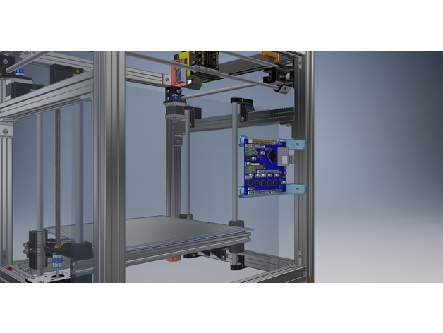
Duet Ethernet Wifi 3030 supports. 3D Print Model
Summary
Simple supports fo fix the Duet Ethernet or Wifi to a 3030 extrusion on my Hypercube Evolution.
Print a Pair.
NOT TESTED YET!
Print Settings
Printer:
Hypercube Evolution
Rafts:
No
Supports:
No
Resolution:
0.2
Infill:
50% Rectilinear -
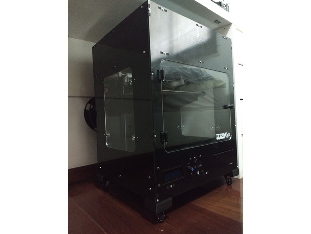
Suporte com Rodinha para GTMAX3D Core A1/A2 3D Print Model
Summary
Sem mistérios para montar:
Quatro rodinhas pequenas e parafusos para elas.
Segue um arquivo projeto para quem usa o Cura. -
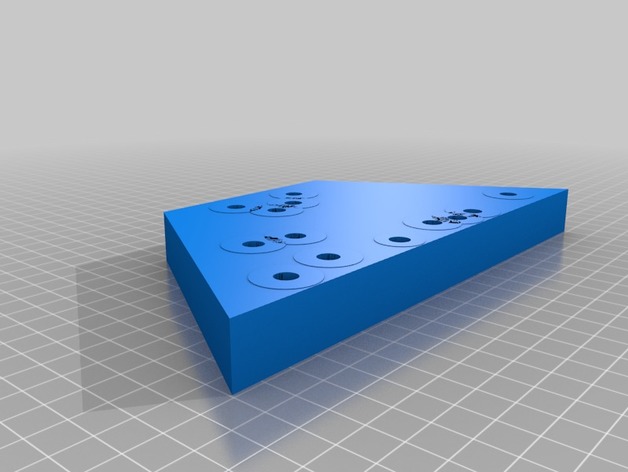
Lee Bench Plates 3D Print Model
Summary
These plates were designed for the Lee Bench Plate Reloading Press Mount LEE 90251. One model is blank except for the two rear locating holes. The second model has all the bolt holes for a majority of Lee reloading presses.
I set infill density at 50% and wall, top and base thickness at 2.4mm with no problems
Bench Plate Link: https://rover.ebay.com/rover/1/711-53200-19255-0/1?icep_id=114&ipn=icep&toolid=20004&campid=5338315919&mpre=https%3A%2F%2Fwww.ebay.com%2Fitm%2F90251-LEE-BENCH-PLATE-KIT%2F221695798614%3Fepid%3D2255119378%26hash%3Ditem339e196d56%3Ag%3Avn8AAOSwB-1Yq26M%3Asc%3AUSPSPriorityMailPaddedFlatRateEnvelope!29588!US!-1
Print Settings
Infill:
50%
Notes:
Set wall, top and base thickness at 2.4mm -
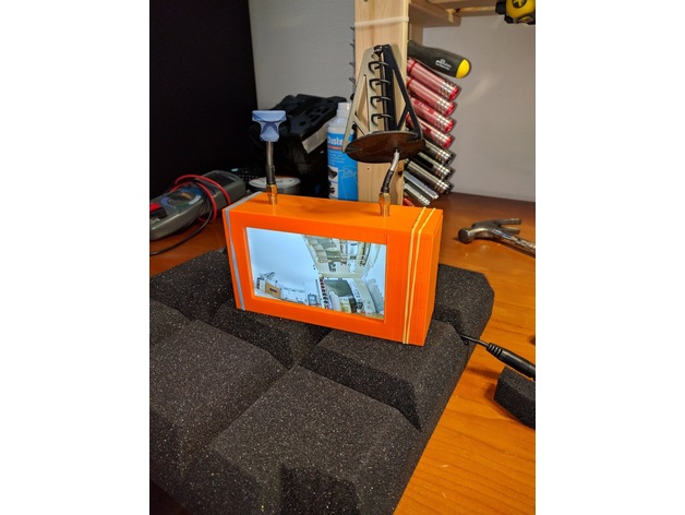
Eachine Googles Two monitor enclosure conversion 3D Print Model
Summary
Custom enclosure to convert a Eachine Googles Two over to monitor.
Works great, but be adviced that it the screen is to small to use for flying. Perfect for spectating. Can be improved, but works good enough for now.
No additional parts needed.
Print Settings
Printer:
Anycubic i3 Mega -
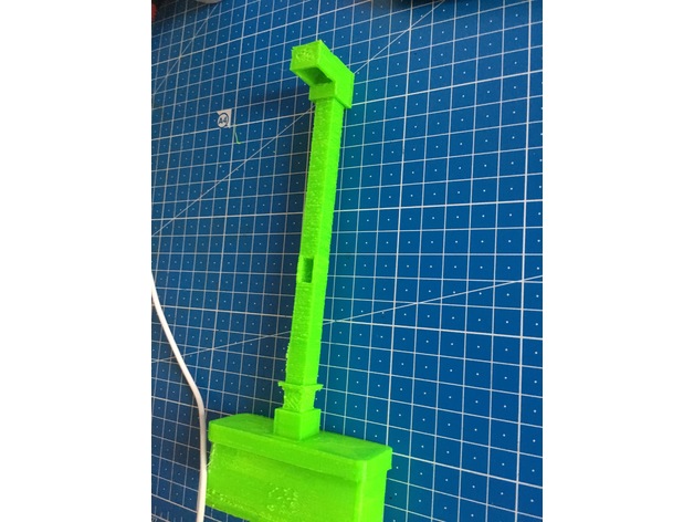
Lithium Battery Tinkerers light 3D Print Model
Summary
I recycled some old 18650 Lithium cells from a broken notebook battery-pack and made small desk lamps for tinkering/soldering/sewing etc.
AS LED any will do but I recommend ones at around 1W to 3W max. the one I used has V_Forward of 3.1V and I_Forward of 350mA.
Which got me to a 3.5 Ohms resistor, at least 1/3 W better 1W resistor.
LEDs
switch
Micro USB charging circuit -
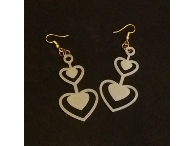
orecchini-cuori 3D Print Model
Summary
earrings
Print Settings
Printer Brand:
Creality
Printer:
CR-10
Rafts:
No
Supports:
No
Resolution:
0.2
Infill:
90% -
Hexagonal Coaster 3D Print Model
Summary
I hope you like it -
![[Snapmaker] Moth Minimal Spool Holder 3D Print Model](https://3dhunt.co/static/2018/05/8c0d570c49e6e758f02555a2bb55095a.jpeg)
[Snapmaker] Moth Minimal Spool Holder 3D Print Model
Summary
Moth styled Minimal Spool Holder.
Heavily inspired by Kelvin8rs Minimal Spool Reel Guidehttps://www.thingiverse.com/thing:2844100
Requires 4 608RS bearings.
Printed with PETG, but anything should do 🙂 Some flex is best though! -
Phone Stand 3D Print Model
Summary
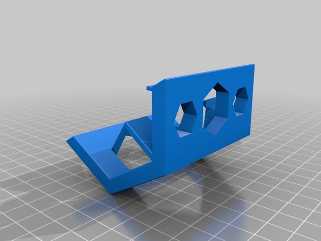
I hope you like it, this is made with an hexagonal shape and you can place your phone horizontally or vertically and the bottom is where the 3 hexagonal shapes are -
Walt Disney Studios Paris Gate homage Tree Ornament 3D Print Model
Summary
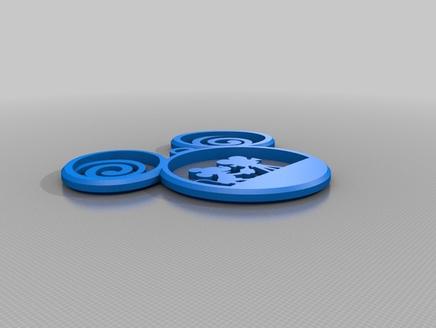
Walt Disney Studios Paris Gate homage Tree Ornament -
38 sided Snub Hexahedron W9 Waterman Polyhedron 3D Print Model
Summary
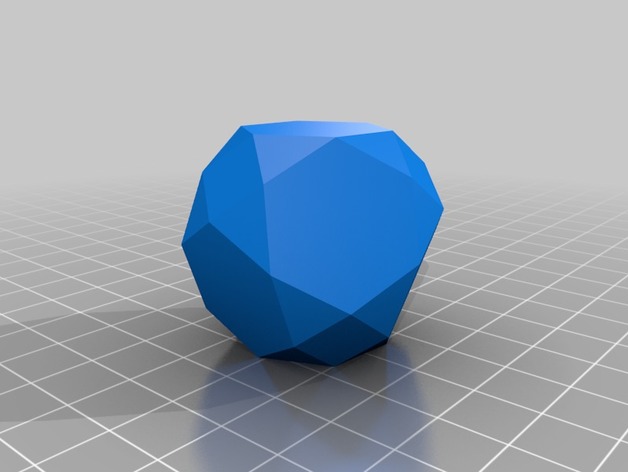
I created this shape by accident as a frame for another shape that turned out to be impossible. I don’t know the name of this object but it is considered a Waterman Polyhedron.
Print Settings
Notes:
if you make this solid, I recommend making it much smaller, otherwise its several hours. If you make it hollow, be careful about the top. -
Hi-Lift Jack Base 3D Print Model
Summary
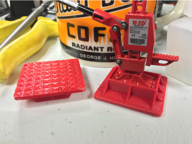
Designed to fit the RC4WD Hi-Lift Jack. These are used to spread the load of the jack base to help from sinking in sand/mud.
Orient flat bases on print bed and glue the two parts together after sanding. -
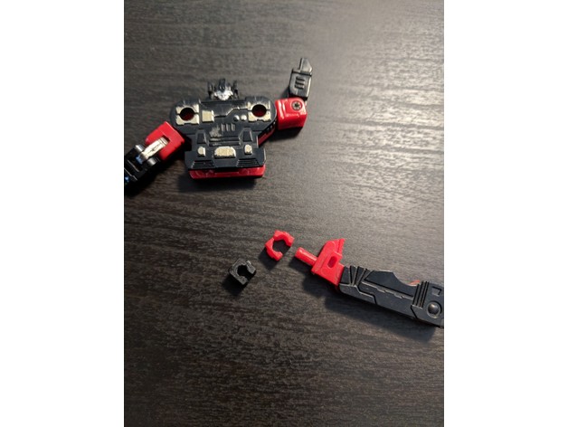
Rumble or Frenzy hip replacement 3D Print Model
Summary
Transformers G1 Frenzy or Rumble cassette hip replacement. .2mm, no supports, 100% infill (if that even matters due to size) some sanding may be required depending on condition of hip/leg areas. Happy to report Frenzy has recovered from his hip surgery and is back in the fight! -
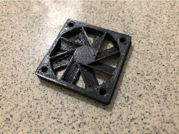
40mm fan shrouds 3D Print Model
Summary
I used this things – https://www.thingiverse.com/thing:2429022 to modified for the 40mm fan since it look like having the best design for the fan shrouds -
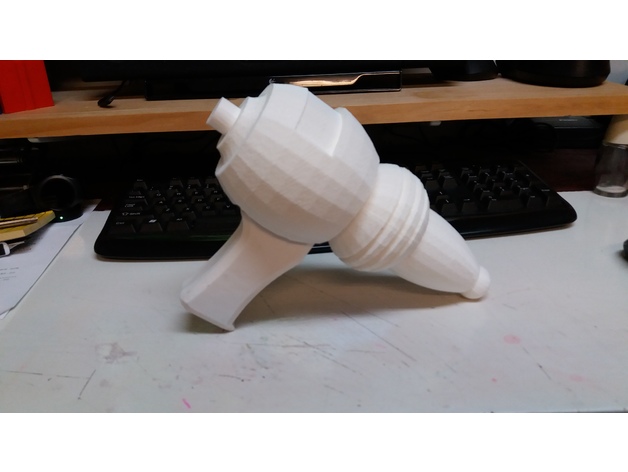
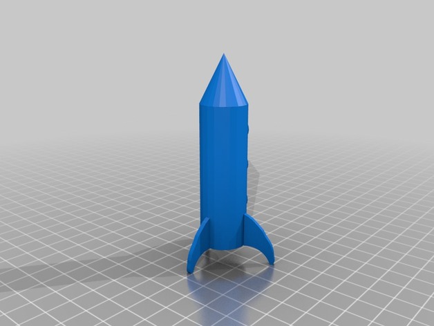
Raygun! 3D Print Model
Summary
A 1950’s style ray gun. hollow inside and could be modified to hold lights using sketchup. -
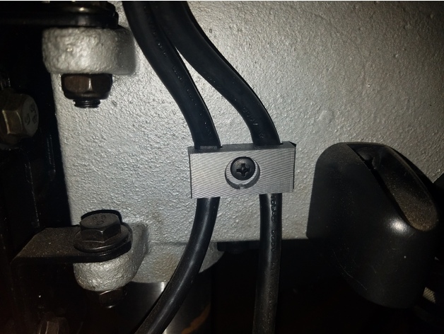
Ryobi Drill Press Power Cable Bracket 3D Print Model
Summary
This is a replacement for the dual power cable management bracket that comes with the 10″ ryobi drill press.
This was designed after the part that comes with the Ryobi 10 Inch with Laser (Model DP103L). It may or may not work with other ryobi drill presses.
https://www.homedepot.com/p/Ryobi-10-in-Drill-Press-with-Laser-DP103L/205503636
Print Settings
Printer Brand:
Prusa
Printer:
i3 MK2S
Rafts:
No
Supports:
Doesn’t Matter
Resolution:
.15mm
Infill:
30% -
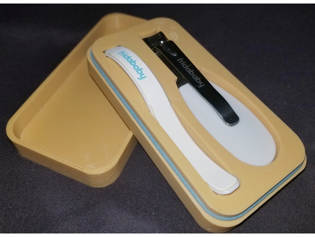
Case for Fridababy NailFrida the SnipperClipper 3D Print Model
Summary
My wife wanted a case for our daughters nail clipper set so what’s better than designing your own? For the very few of you, if any, that have the Fridababy nail clipper set and in desperate need of a case, here you go =).
Print Settings
Printer Brand:
Prusa
Printer:
i3 MK2S
Rafts:
No
Supports:
No
Resolution:
.2
Infill:
10%
Notes:
There are 2 tops you can choose to print. -
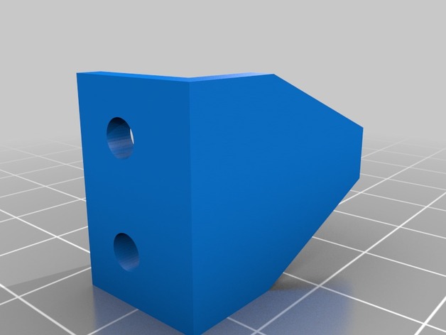
Blind Holder 3D Print Model
Summary
These are used to hold down blinds in a camping trailer
Print Settings
Printer:
maker select plus
Rafts:
No
Supports:
No
Resolution:
0.2mm
Infill:
100% -
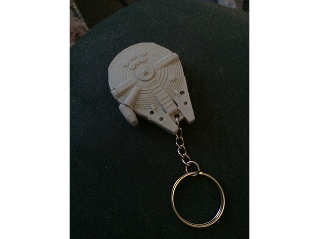
Millennium Falcon RFID fob housing 3D Print Model
Summary
A housing for an RFID Fob, HID ProxiKey 3, I believe.