Summary
Get ready with all the parts along with the additional requirements on each parts. Assemble the part according to the sketch on the lower left corner on the sketch image. Place the copper plate on the working area. Upload the gcode file for PCB plotting. After the process is done you get a PCB, where you can solder the remaining electronic devices to get a circuit board.
Materials Needed
Requirements
Shaft. Dimension: 6mm (Diameter), Material: Stainless Steel(SS), Length: 8cm
Circlips. Inner Diameter: 5mm , Qty: 2
Metal Washers: Inner Diamerter: 6.5mm, Outer Diameter:12. Qty: 3
Spring: Inner Diameter: 6mm
Shaft Holder. (3D Printed). File Attached as: Upper_part.stl
M3 SS Bolts. Qty: 4
Metal Washers. Inner Diameter :3mm Qty: 4
Fiber washers. Inner Diameter: 3mm Qty: 4
Spring Washers. Inner Diamerter: 3mm. Qty: 4
M3 Nuts. Qty: 4
Preparation
Making Parts Ready
1: The File attached under the name of Upper_part.stl must be printed before we start assembling stuffs (Two of such parts is needed). This might take a moment but please be patient.
2: After the Parts have been successfully printed, We need to calibrate the hole of 6mm which s there right on the middle of the work-piece. For this Take the 6mm shaft and heat it a little ( The Process which was used meanwhile was placing the Shaft on the Drill, Rotating it at its maximum speed and Applying Sandpaper on its Surface. This Process will not only heat he shaft but also will smooth the shafts surface.) The heated shaft is inserted in the hole so that the shaft moves through the hole with less resistance.
3: Making Circlip Slots, Mark 10mm and 50mm from one side of the rod (Let this side be named as A and other be B) Make the slots for the Circlip slots on those marked points. The method which we used was placing the shaft on the drill and then placing a hacksaw blade on the marked line)
4: Sharpening the Shaft, the other side of the shaft i.e B has to be sharpen. We used an angle grinder with a buffing blade, placed the shaft with some constant angle and rotated the shaft.
5: Ready the copper plate, The copper plate of required dimension was sliced out and one face of it is perfectly sketched with black sketch pen.
Assembling Parts
Gather your Tools
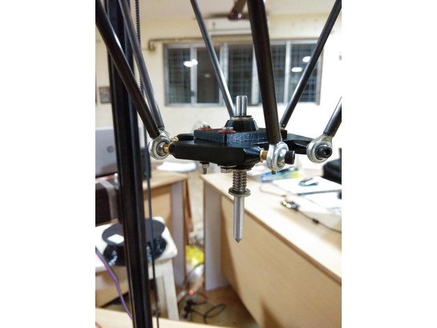
Bolt both the 3D printed part, sandwiched between the bed. Apply Fiber washer below bolt head and Metal Washer right before spring washer and nut. Rest of the part should be assembled as the sketch image attached.
Feel free to ask any doubts regarding the assembly.