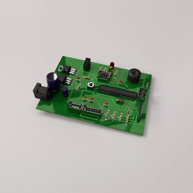
CIRCUIT BOARD===============================- Modeled in Blender.- Preview image rendered using cycles.- All scene are included in .blend files.- Poly count are before sub division- Great for close up render.- All parts and materials are logically named.OTHER FORMATS=================- 3ds MAX- COLLADA (.dae)- Autodesk FBX- OBJ
Tag: PCB
-
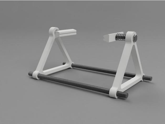
Simple PCB Holder 3D Print Model
Summary
A simple holder for PCB work.
Print 2 of each STL file.
Push an M6 bolt through the top hole of a frame, slip on a spring (washers optional) and glue into a block.
Repeat.
2 pieces of M8 threaded bar through the bottom 2 holes. slide together to hold PCB, end frames will grip the threaded rod.
Wrap an elastic band around the each end of each thread if required or add some M8 nuts to cinch it up.
Simple 🙂
Hardware required
M6 bolt x2
spring x2
washers x4 (optional)
M8 threaded bar – cut to any length you want (or 8mm wooden dowel)
Hot-melt glue or similar
Rubber bands – to hold frames (optional)
M8 nuts – to hold frames (optional)Print Settings
Printer:
GEEETech i3 Pro B
Rafts:
Yes
Supports:
Doesn’t Matter
Resolution:
0.2
Infill:
25%Post-Printing
The glue only needs to be strong enough to prevent the spring pushing the block off the end of the bolt.
The spring should be able to grip the PCB without damaging it. (TIP: I cut the springs out of pump-action soap dispensers – just the job 🙂 – or buy a tray of assorted springs off eBay for a few quid.
How I Designed This -
PIR Sensor 3D Model
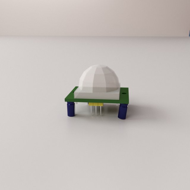
PIR SENSOR=================================- Modeled in Blender.- Preview image rendered using cycles.- All scene are included in .blend files.- Great for close up render.- All parts and materials are logically named.OTHER FORMATS=================- 3ds MAX- COLLADA (.dae)- Autodesk FBX- OBJ
-
Trimpot 3D Model
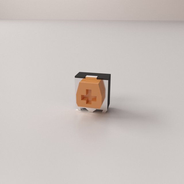
TRIMPOT=================================- Modeled in Blender.- Preview image rendered using cycles.- All scene are included in .blend files.- Great for close up render.- All parts and materials are logically named.OTHER FORMATS=================- 3ds MAX- COLLADA (.dae)- Autodesk FBX- OBJ
-
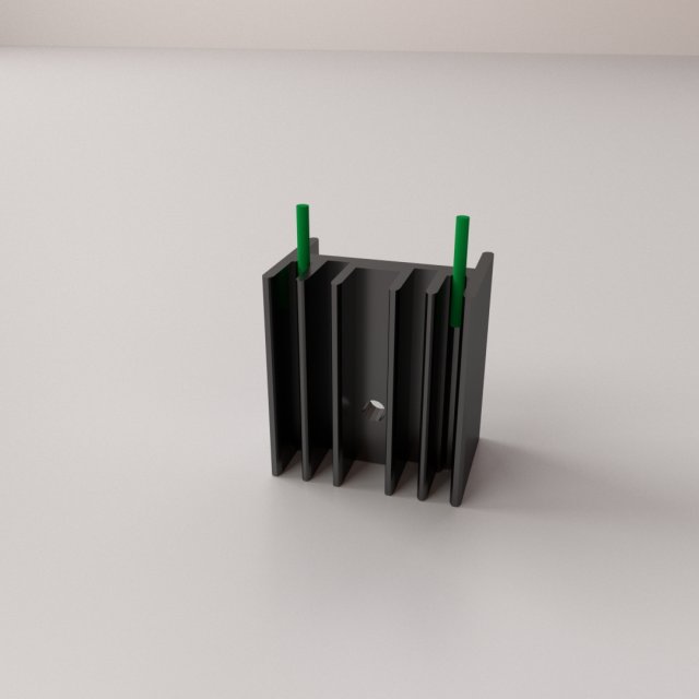
Heatsink v2 3D Model
HEATSINK V2=================================- Modeled in Blender.- Preview image rendered using cycles.- All scene are included in .blend files.- Great for close up render.- All parts and materials are logically named.OTHER FORMATS=================- 3ds MAX- COLLADA (.dae)- Autodesk FBX- OBJ
-
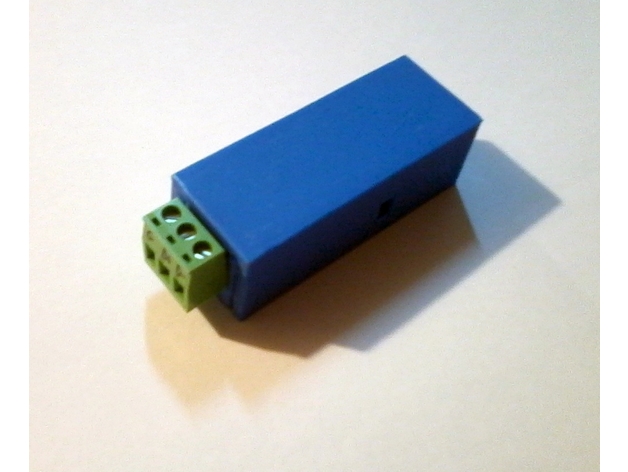
Case for PCB USB to RS485 3D Print Model
Summary
This box to house a small usb to rs485 converter. Box without holes, with side latches.
Print Settings
Printer:
RepRap(Marlin) Rafts:
Doesn’t Matter Supports:
Doesn’t Matter Resolution:
0.2 Infill:
30% + -
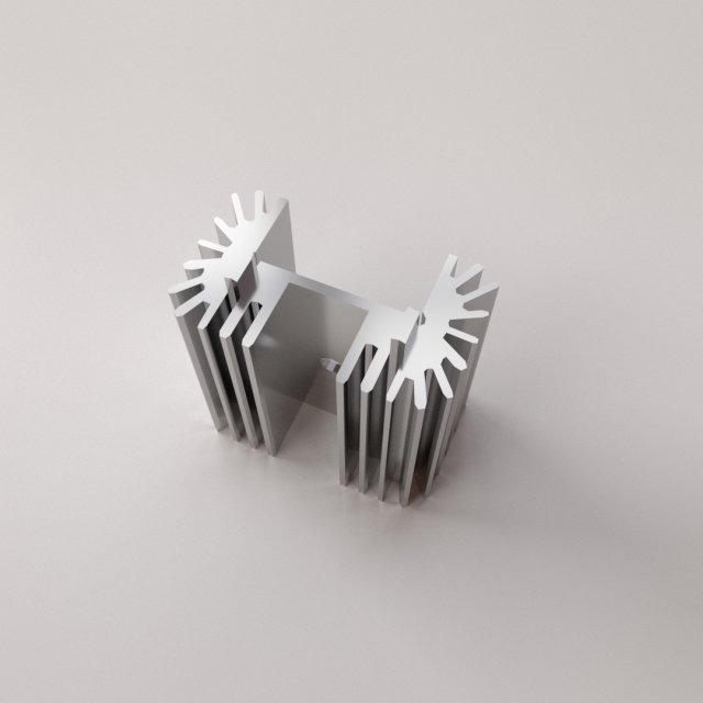
Heatsink 3D Model
HEATSINK=================================- Modeled in Blender.- Preview image rendered using cycles.- All scene are included in .blend files.- Great for close up render.- All parts and materials are logically named.OTHER FORMATS=================- 3ds MAX- COLLADA (.dae)- Autodesk FBX- OBJ
-
PCB Vise 3D Print Model
Summary
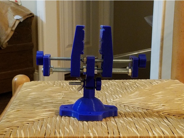
This is a PCB vice.
The base can be screwed down for better stability.
The top can be tilted up or down. The hex stem can be rotated move the clamp without having to move the base.
Printed parts:
PCB_clamp_base x1
PCB_clamp_stem x1
PCB_clamp_center x1
PCB_clamp_end_piece x2
PCB_clamp_face x2
PCB_clamp_knob x1
PCB_clamp_knob_big x2
Purchased Parts:
Hex screw 1/4 x 20 x 6″ x2
Carriage Bolt 1/4x20x3.5″ x2
Carriage Bolt 1/4x20x1.5″ x1
Hex Nut 1/4×20 x10
Hex Nylon Lock Nut 1/4×20 x2
Wing Nut 1/4×20 x1
Print Settings
Printer:
Tronxy X3A Rafts:
No Supports:
Yes Resolution:
0.2mm Infill:
20% Notes:
Brim was used on the stem, clamp faces, knobs
Post-Printing
Instructions:
Insert a hex nut into the hex shaped hole in each of the clamp faces. It can be heated and pushed in or “plastic soldered” for a more permanent fit. These will be used to move the clamps.
The 6″ hex bolts, along with the hex nuts, are used to space the parts. The nylon lock nuts are used at the end so they won’t fall off.
The small knob is used on the carriage bolt that attaches the clamp center to the stem.
The bigger knobs are attached to the carriage bolts that move the clamp faces.
The knobs should be a press fit into the bolts.
See the pictures for how to assemble. One pic shows the nuts loosened, another shows it with everything tightened up.
How I Designed This
This was designed using Design Spark.
Due to the threads on the bottom screws, and the off center drive, the movement of this isn’t very smooth. -
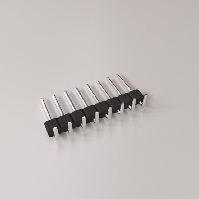
Curved Male Header 3D Model
CURVED MALE HEADER=================================- Modeled in Blender.- Preview image rendered using cycles.- All scene are included in .blend files.- Great for close up render.- All parts and materials are logically named.OTHER FORMATS=================- 3ds MAX- COLLADA (.dae)- Autodesk FBX- OBJ
-
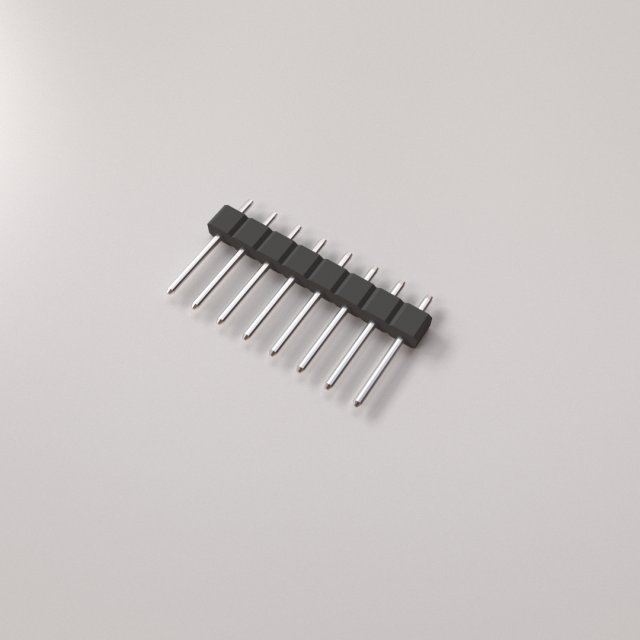
Straight Male Header 3D Model
STRAIGHT MALE HEADER=================================- Modeled in Blender.- Preview image rendered using cycles.- All scene are included in .blend files.- Great for close up render.- All parts and materials are logically named.OTHER FORMATS=================- 3ds MAX- COLLADA (.dae)- Autodesk FBX- OBJ
-
PCB Etching with 3D Printer Agitatior 3D Print Model
Summary
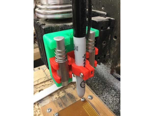
I made Tech2C’s Pen holder https://www.thingiverse.com/thing:2459624
I used it on my Milling machine to apply sharpie ink as an etch resist.
Then I used my 3D printer to heat and agitate the Ferric Chloride solution with the pcb in it.
GCODE
g1 y0 f4000
g1 y50
g1 y0 f200
g1 y50
make many copies of this. Takes about 15 seconds to execute.
You can see the sample pcb traces that I produced using this technique. I would increase the overlap of the sharpie lines and print twice to ensure a good resist. the thin lines were just one layer of sharpie. they worked but got a little undercut.
I will add a video later showing the etching setup.
I found that setting my bed temp to 100C kept the Ferric Chloride solution below the recommended 55C maximum with my plastic tray which is pretty thick.
If anyone has a great way to get pcb gerbers into Fusion 360, please message me or comment on this thing -
ANYCUBIC END EFECTOR FOR PCB PRINTING 3D Print Model
Summary
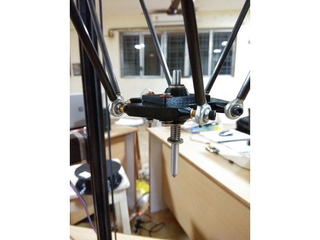
Get ready with all the parts along with the additional requirements on each parts. Assemble the part according to the sketch on the lower left corner on the sketch image. Place the copper plate on the working area. Upload the gcode file for PCB plotting. After the process is done you get a PCB, where you can solder the remaining electronic devices to get a circuit board.Materials Needed
Requirements
Shaft. Dimension: 6mm (Diameter), Material: Stainless Steel(SS), Length: 8cm
Circlips. Inner Diameter: 5mm , Qty: 2
Metal Washers: Inner Diamerter: 6.5mm, Outer Diameter:12. Qty: 3
Spring: Inner Diameter: 6mm
Shaft Holder. (3D Printed). File Attached as: Upper_part.stl
M3 SS Bolts. Qty: 4
Metal Washers. Inner Diameter :3mm Qty: 4
Fiber washers. Inner Diameter: 3mm Qty: 4
Spring Washers. Inner Diamerter: 3mm. Qty: 4
M3 Nuts. Qty: 4
Preparation
Making Parts Ready
1: The File attached under the name of Upper_part.stl must be printed before we start assembling stuffs (Two of such parts is needed). This might take a moment but please be patient.
2: After the Parts have been successfully printed, We need to calibrate the hole of 6mm which s there right on the middle of the work-piece. For this Take the 6mm shaft and heat it a little ( The Process which was used meanwhile was placing the Shaft on the Drill, Rotating it at its maximum speed and Applying Sandpaper on its Surface. This Process will not only heat he shaft but also will smooth the shafts surface.) The heated shaft is inserted in the hole so that the shaft moves through the hole with less resistance.
3: Making Circlip Slots, Mark 10mm and 50mm from one side of the rod (Let this side be named as A and other be B) Make the slots for the Circlip slots on those marked points. The method which we used was placing the shaft on the drill and then placing a hacksaw blade on the marked line)
4: Sharpening the Shaft, the other side of the shaft i.e B has to be sharpen. We used an angle grinder with a buffing blade, placed the shaft with some constant angle and rotated the shaft.
5: Ready the copper plate, The copper plate of required dimension was sliced out and one face of it is perfectly sketched with black sketch pen.Assembling Parts
Gather your Tools
Bolt both the 3D printed part, sandwiched between the bed. Apply Fiber washer below bolt head and Metal Washer right before spring washer and nut. Rest of the part should be assembled as the sketch image attached.
Feel free to ask any doubts regarding the assembly. -
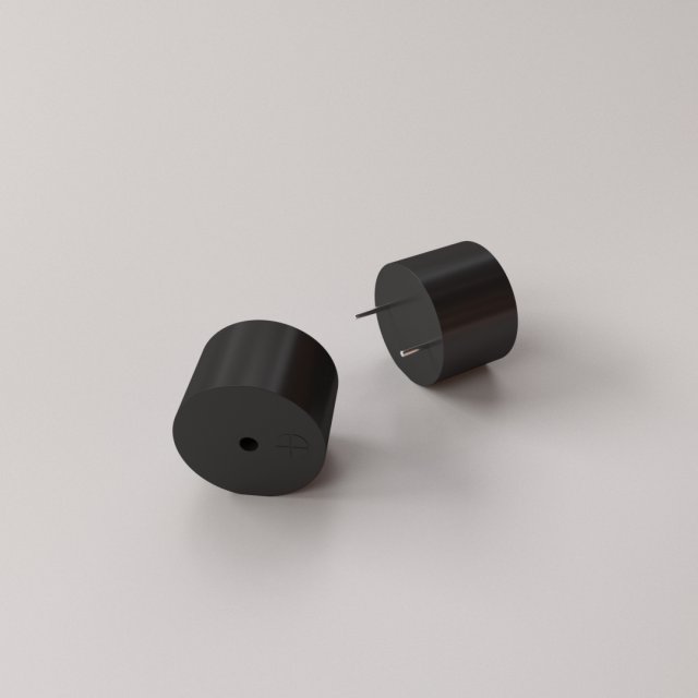
Buzzer Piezo 3D Model
BUZZER PIEZO=================================- Modeled in Blender.- Preview image rendered using cycles.- All scene are included in .blend files.- Poly count are before sub division- Great for close up render.- All parts and materials are logically named.OTHER FORMATS=================- 3ds MAX- COLLADA (.dae)- Autodesk FBX- OBJ
-
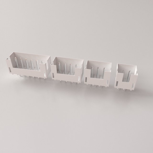
XHB Connector 3D Model
XHB Connector=================================- Modeled in Blender.- Preview image rendered using cycles.- All scene are included in .blend files.- Great for close up render.- All parts and materials are logically named.OTHER FORMATS=================- 3ds MAX- COLLADA (.dae)- Autodesk FBX- OBJ
-
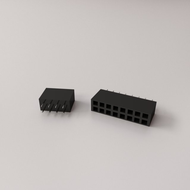
Female Header 3D Model
FEMALE HEADER=================================- Modeled in Blender.- Preview image rendered using cycles.- All scene are included in .blend files.- Great for close up render.- All parts and materials are logically named.OTHER FORMATS=================- 3ds MAX- COLLADA (.dae)- Autodesk FBX- OBJ
-
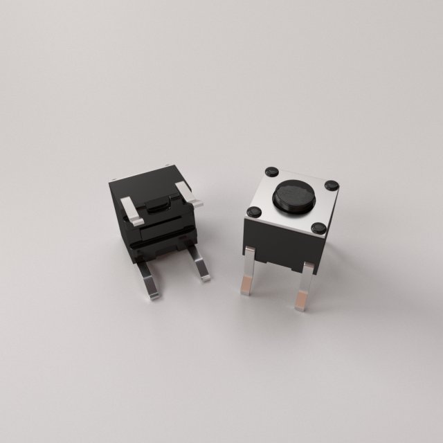
Tactile Push Button 3D Model
TACTILE PUSH BUTTON=================================- Modeled in Blender.- Preview image rendered using cycles.- All scene are included in .blend files.- Poly count are before sub division- Great for close up render.- All parts and materials are logically named.OTHER FORMATS=================- 3ds MAX- COLLADA (.dae)- Autodesk FBX- OBJ
-
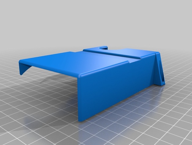
Cyclone PCB Modified Electronics Cover 3D Print Model
Summary
The zip ties on the Y linear bearing holders were rubbing against the electronics cover on my machine. So I made this new one that has a channel to give more clearance for the zip ties.
But really, it’s probably better to just relocate the electronics elsewhere. -
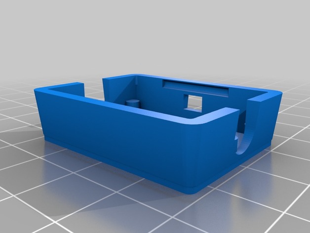
SDR Amplifier PCB Case 3D Print Model
Summary
Based on the Case of 3cky i adjusted a bit the code to create a case for my SDR LNA. All the credits go to him.