Summary
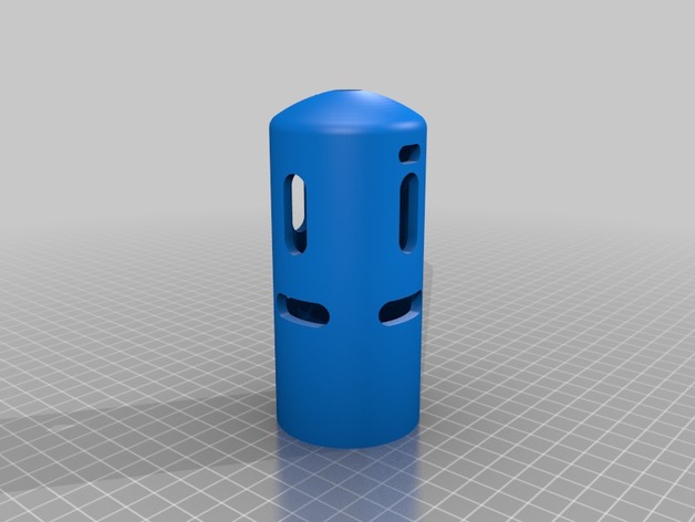
This year, we’re using a few redline motors on our robot. They’re the kind of motor that have tabs you solder the wire to, but they seem a bit delicate and easy to get torn off if a lose wire got caught on something. To protect the motor and our service loop, I created a cover to keep the tabs and loop nice and safe.
When you put it on, you might need a layer or two of electrical tape depending on the motor, pahse of the moon, days untill next leap year, ect.
Print Settings
Printer Brand:
LulzBot
Printer:
TAZ 6
Rafts:
Yes
Supports:
No
Resolution:
0.3 mm
Infill:
100 %
Notes:
If you use the model with what looks like tubes running all over, dont use supports, the tubes are supports. Otherwise, you’ll need to create your own supports.
First layer hieght is 0.36 mm.
Post-Printing
You will need to remove the supports, which for me was a bit of a pain.
Step One: Remove “looser” supports
Us a pair of needlenose pliers or simailer to remove the majority of the support on the outside and inside of the cover. Dont go crazey trying to get supports that stick too strongly, they”ll come of in one of the other steps.
Step Two: Remove supports from the cuttouts
Use a scratch awl/ center punch and hammer to punch out the supports from inside the cutouts and any strgglers you couldn’t get with the pliers (except the ones where the raft was, leave those for the next step). I find it helpful to put the cover in a vice and lightly – I repeat- lightly clamp in in and let it settle to the bottom, then tap the supports out.
Step Three: Remove the supports from where the raft was
Usually, I use a chisle to remove supports like this, but had trouble executing. Instead, I held the peice in a pair of vise-grips and used a belt sander to remove them, which leaves a rough, woodstained section, but is probably smoother (and certanly faster) than trying to get them off with pliers.
How I Designed This
This tutorial is designed to work to make a cover for any motor you may have, using the redline motor as an example. Screenshots were taken in Onshape.
Step One (a): Create the main body
On whatever plane you choose, create a sketch consisting of a line half the diamiter of your motor plus relief (e.g. [(1.77/2 in)+0.25 mm]) from the origin and as long as you want your cover to be tall ( because part of the purpose of my cover was to proect a service loop, I left a lot of room up there). Also create a rounded top as tall or flat as you wish. The top is pretty unimportant and you can just eyeball it. I like to fillet the connection between the line and the arc to make it nice and smooth.
(b)
Offset this entire sketch as thick as you see fit, I used 0.15 in. Also connect the offset sketch to the original one with a line, and be careful with the top arc. Make sure that line is parellel with whichever direction is “up” and even with the offset arc, then connect those two lnes with another line (see close up picture).
Don’t forget to connect the two arcs properly!
(c)
Revolve that sketch a full 360 degrees into a new solid, using the line parrellel to the “up” direction and in the center of where the solid will be as the revolve axis.
Step Two (a): Make cutouts for air cerculation and wire routing.
After offseting a plane the radius of the hollow cylinder you’ve created, sketch slots for any air circualation cutouts in your motor. If you’re making a cover for a sealed motor, like a CIM, dont worry about air. You can find the distance for your cutouts by eyeballing with a caliper or ruler about how far up they start and stop, and to make it nice rounding off the edges with arcs.
(b)
Take any sketches you made for cutouts and extrude them all the way through, or use emboss if your software has it, which is a feature Onshape lacks. Another, much more annoying thing to be witho is the abillity to pattern your holes, so the only way to get more cutouts is to duplicate you sketch onto a perpendicular plane and extrude it through again. I don’t think you can rotate the part or make a plane wuth a costum angle, but if I’m wrong please correct me.
(c)
Now you’ll need cutouts for your wire to exit from, unless you’re cool with them coming through the other cutouts (i think that looks messy). Create two lines. The distance between them is equal to the diamiter of your wire plus relief. Make them as long as the diamiter of your wire times two plus relief, then round the edges with arcs to make it nice. Extrude this, but not all the way through. I also like to add one coming out the top so you’ve got options. The diamier of the hole I extrude out the top is the diamiter of the wire times two plus relief.
Step Three: Add finishing touches
I like to chamfer all of the parts you’ll have to stick things through or into to make it easier to align. I chamfered the large opening for the motor to go through and the two wire routing holes.
Congrats, you’re done!
Enjoy your cosutom motor cover, maybe even engrave your team name or number on it!