Summary
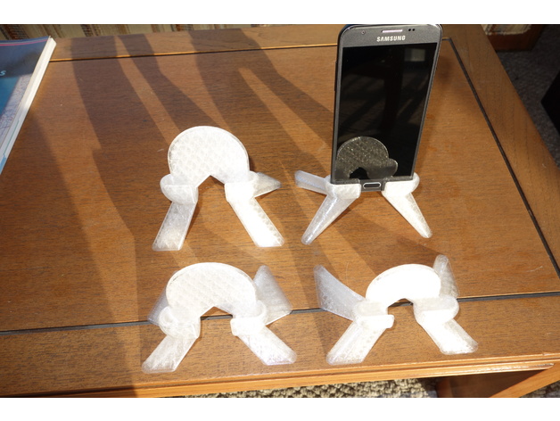
This is a parameterized phone stand.
The parameters are currently set for the Samsung Galaxy Luna Pro
This was done in both OpenSCAD and FreeCAD
To adjust this design to match your phone, in FreeCAD, edit the spreadsheet, in OpenSCAD, edit the variables at the beginning of the file.
I did this project as a way to learn how to use FreeCAD
I did this first in OpenSCAD, and completed it fairly quickly. I was figuring out what I was designing at the same time as I was designing it, so the code is horrible. It was a rather straightforward design in OpenSCAD, just a bunch of manual geometry.
In FreeCAD, I already knew what I was trying to design since I had done it in OpenSCAD. In FreeCAD it was mostly fighting the tool, figuring out how I was causing it to break, and how to avoid the pitfalls of FreeCAD. I had a lot of much appreciated help from the people at the FreeCAD forum.
FreeCAD had just come out with version 0.17 as its stable version. I had tried 0.16 and found it unstable, I had tried early versions of 0.17, and it looked promising, but was too much in flux. the stable version of 0.17 seems just stable enough to be usable.
I must have started over in FreeCAD at least 20 times. As a result the final design is much more polished than the OpenSCAD design.
Things I learned in FreeCAD:
Bodies can be rotated and translated, but the boolean tools for Bodies will ignore the rotation and translation, and use the original position of the body.
When working on a body, there is no way to translate or rotate what has already been done, so everything you are working on must be done in the final position.
You can create a reference plane (or a set of reference planes) that are rotated and offset from the default coordinate system, so you can work in this alternate coordinate system. This gets the same effect of rotating what you had previously done, but you must effectively rotate and move your coordinate system before you start building the part you wish to rotate or offset.
You can build your object with parameters in a spread sheet, but not all operations will update when parameters are changed.
There are multiple different workbenches. Operations in one workbench are not always available in another.
Objects designed in one workbench are not always usable in another.
In this design I did most of the initial work in “Part Design”, but I needed to do a loft that was only available in the “Part” workbench. The loft can use a face, or a sketch, but if you have a body from the Part Design workbench, you can’t select a face on it and use that in a loft. One must first make a clone of the object, then go to the “Draft” workbench, select the face you wish to use, select “Create Facebinder Object”, then you can go back to the “Part” workbench, and use that Facebinder Object as a face for the draft. The loft can use a sketch from the “Part Design” workbench, but if it has links to a spreadsheet as it will in a parameterized design, it will break. Instead, one must put the sketch in a body, Pad it into a 3D object, and then go through the above procedure so that you can for a face so you can select the face that was defined in the sketch, and use that as part of the loft.
The sketch tool has some issues one needs to know about. It does not always catch when an object is over constrained. One of the most common failure here is when a line with an horizontal constraint has its endpoints mirrored by the vertical axis, the horizontal constraint becomes redundant, but this is not noticed by the tool. This often causes problems later, and is sometimes difficult to trace back to the redundant constraints. If there is a problem with a sketch, sometimes it won’t let you edit numerical constraints to fix the problem, and one must delete some constraints before you can re-add the corrected constraints.
FreeCAD has some architectural issues. whenever the number of edges in an object change, they are arbitrarily renamed. Since later steps are often linked to earlier steps, they end up being linked to the wrong edges. 0.17 added a work around to this issue by allowing sketches to be linked not to the object, but to reference planes. Fillets are still a problem though since they must be linked to edges. The common suggestion is to do the fillets last. Fillets also have trouble when their edges overlap.
Boolean operations have trouble with tangential surfaces. If you wish to do a boolean operation on two objects which have a face in common, it is very likely to fail. The work around is to offset faces so the objects overlap, or don’t touch. It can sometimes be difficult to find the offending face or edge.
FreeCAD does not allow adding comments to sketches, about the only place comments can be added is to the spreadsheet.
Print Settings
Printer Brand:
LulzBot
Printer:
TAZ 6
Rafts:
No
Supports:
No
Resolution:
0.4 mm layers
Infill:
20
Notes:
All overhangs are limited to about 45 degrees, so no support was needed.
Parameterized phone stand 3D Print Model