
Summary
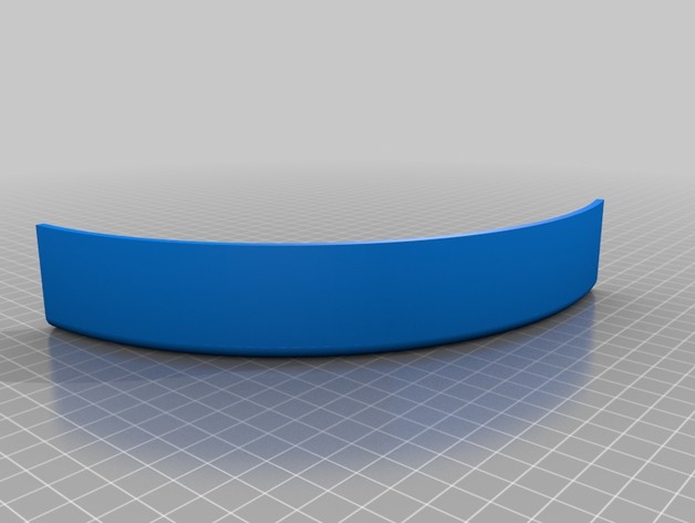
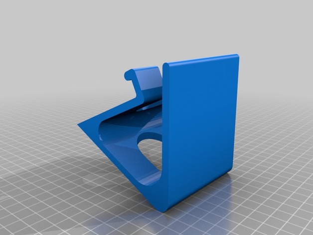
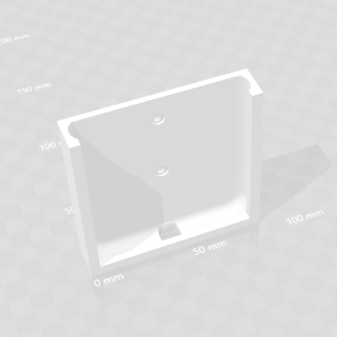
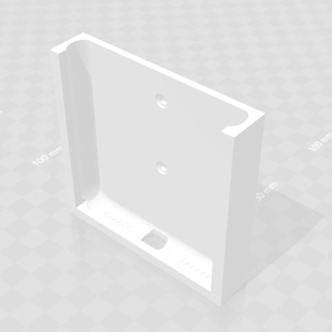
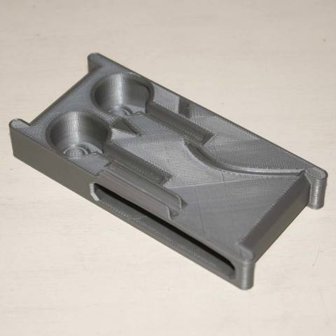
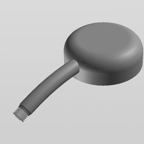
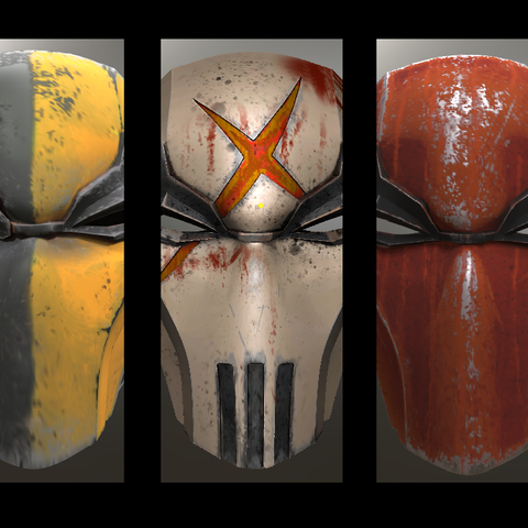
Eye piece mount for a telescope. mounts with #8 screws and has insets for m3 nuts for tighting.
based on this: https://www.amazon.com/Orion-07215-Schmidt-Cassegrain-Finder-Scope/dp/B0000XMY4C/ref=pd_bxgy_421_2?_encoding=UTF8&pd_rd_i=B0000XMY4C&pd_rd_r=30M3MMWJ0VG3H1DHRPXM&pd_rd_w=ySYI2&pd_rd_wg=fIGYo&psc=1&refRID=30M3MMWJ0VG3H1DHRPXM&dpID=41BkDqiTDKL&preST=_SX300_QL70_&dpSrc=detail
Category: 3D Print Models
Premium & 3D Print models ready to be 3d printed. 3D Print Models and Free 3D Print Models are available for download in several formats including .STL, .3DM, .OBJ, .3DS, .DAE, .SKP, .BLEND, .DWG, .DXF, .STEP and much more. If you’re in search of high-quality 3D printed assets, we have a huge library of 3d print models for any of your needs. Also you can visit 3D Models and All 3D Models category.
-
Telescope finder scope mount 3D Print Model
-
FinWing Traveler T1160 Split Mount 3D Print Model
Summary
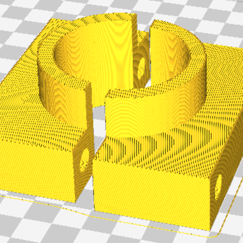
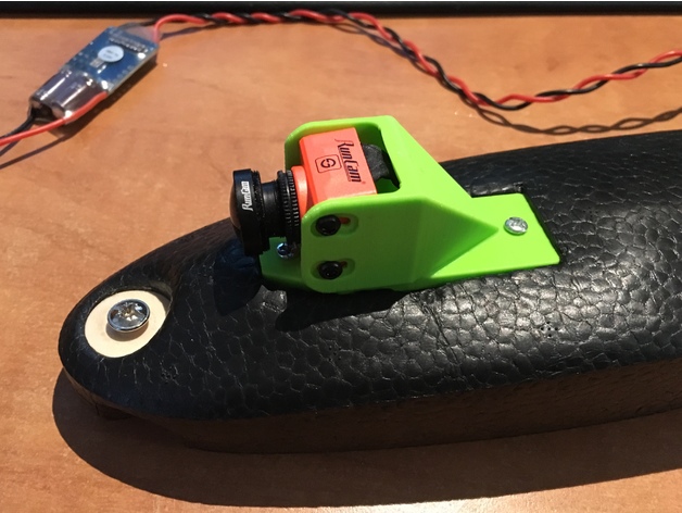
Split Mount for FinWingHobby Traveler T1160.
Works best with board mount https://www.thingiverse.com/thing:2829533 -
Ultimaker 2 Titan Fixture 3D Print Model
Summary
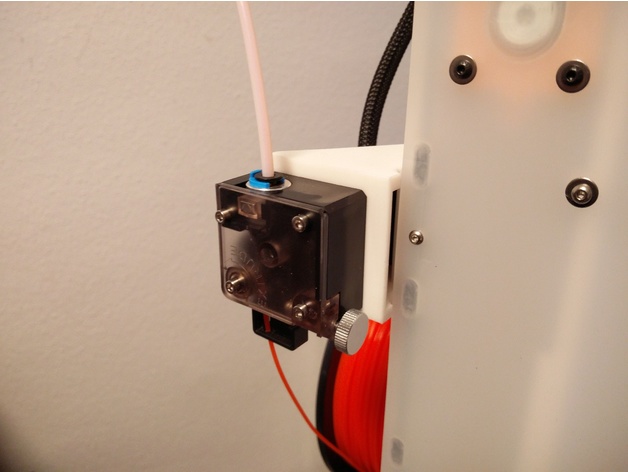
The motor shaft of most of the steppers is too short as to use it inside the UM2 to connect the Titan Feeder.
Therefore i made this 90° angled fixtures for the Titan to use the existing holes.
Print Settings
Printer Brand:
Prusa
Printer:
Prusa Clone
Rafts:
Doesn’t Matter
Supports:
Doesn’t Matter
Resolution:
0.3
Infill:
20% -
Man Head 3D Model
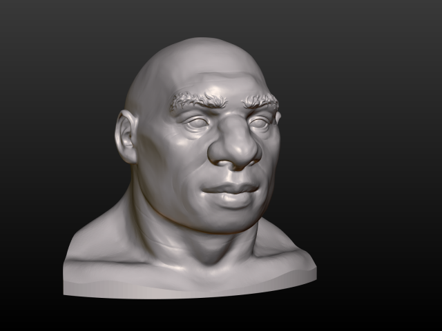
High Poly man Head.Measure units are meters, it has about 38 cm in height.Mesh is manifold with no bad contiguous edges.Files available in two versions:1)Man_Head-01 contains 795747 faces2)Man_Head-02 contains 52948 facesAvailable formats: .blend, fbx, .obj, .stl, .3ds, .dae.
-
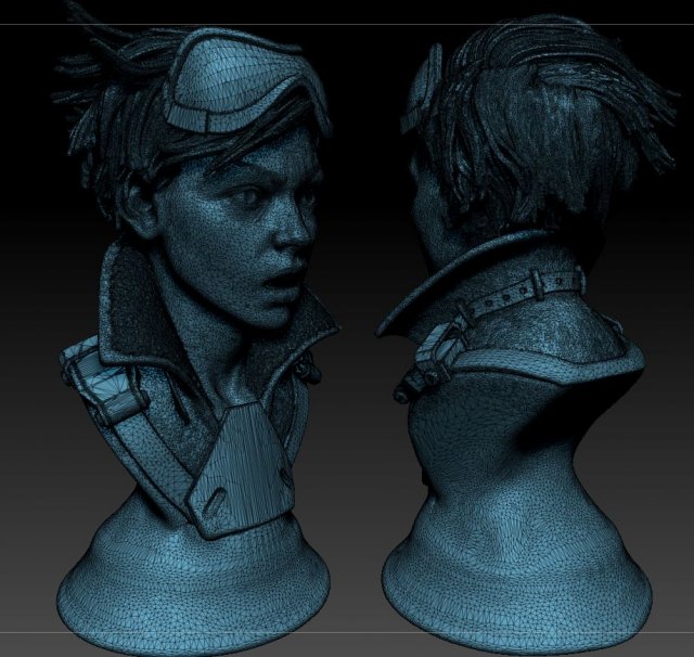
Overwatch Tracer Bust – Fan Art Free 3D Model
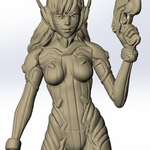
This is a bust of Tracer from Overwatch, I made this as fan art and since Im not licensed to use this for profit I’m giving it away for free! Please note that this cant be used in any retail/professional sense and is for entertainment/educational purposes only.
-
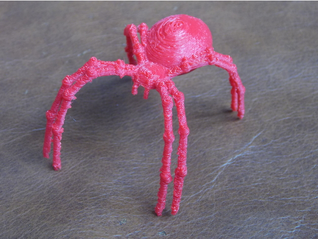
Filament Guide Spider 3D Print Model
Summary
So! Another filament guide to keep my line from getting tangled, and to look kinda cool, like he’s spinning webs for The Machine… He sits on my Y-Axis motor, on a clip that grips the stepper.
(Zip-tied on for now, pending gluing onto the clip…)
Print Settings
Printer:
FLSUN Prusa i3
Rafts:
Yes
Supports:
Yes
Resolution:
0.1mm
Infill:
10% rectilinear
Notes:
Printed in PETG, a challenging print, with the legs being 1.5mm in diameter. I couldn’t have been able to get this resolution and such small diameters printed successfully before I calibrated my E-steps/mm and my extrusion multiplier (with the _40x10.stl ), and these YouTube videos;https://www.youtube.com/watch?v=w_Wb0i0-Qvo,https://www.youtube.com/watch?v=cnjE5udkNEA&t=298s
Got the idea to print upside down from woodk, https://www.thingiverse.com/thing:1619849 -
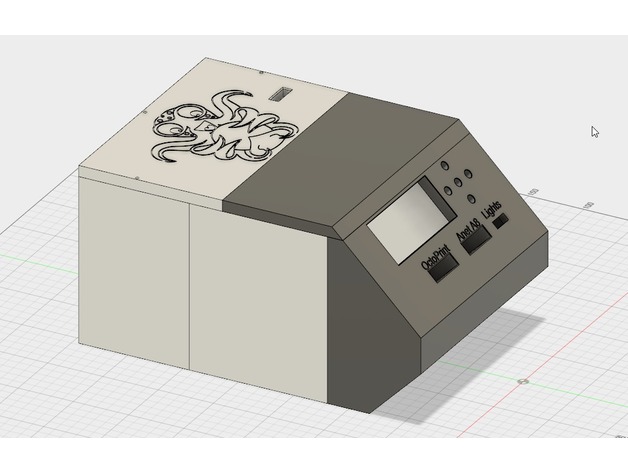
No Touch Screen Remix 3D Print Model
Summary
Just removed the touch screen from the front and move the Anet A8 screen.
Original Thing here: https://www.thingiverse.com/thing:2748195 -
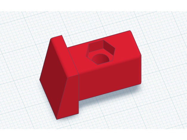
KTM Rear Frame Plug Fender Mount 3D Print Model
Summary
The rear fender on KTM XC, EXC, and XC-W is fastened to the rear of the frame with 2 screws. The tubes on the frame are rectangular and have a plastic plug in the end with a threaded barrel for an M5 screw to go into. My dealer cannot get this part, and I cannot find it online anywhere. This is a perfect replacement for it. It may work on other KTM motorcycles/dirt bikes as well, but I don’t have others to test it on. This one definitely works on the 2013 XC-W. Please let others know in the comments if it works on others.
You will need an M5 metric nut to press into the hex cutout in the plug using a pliers, I picked up the nuts at Home Depot. You should use a stainless one if possible for durability, but any standard M5 nut should work.
Make sure you print with supports and 100% fill.
Print Settings
Printer:
MP Select Mini v2
Rafts:
Doesn’t Matter
Supports:
Yes
Resolution:
.13125
Infill:
100
Notes:
Walls – 1.4mm
Top/Bottom – 1mm
No Coasting
Post-Printing
Remove the supports and clean up the edges with a razor blade or knife.
Press an M5 nut into the hex cutout with a pliers. Use stainless for durability. The edges of the part may need a bit of sanding/filing to fit in the frame, it’s meant to fit tight. You can tap it in with a mallet pretty easily.
How I Designed This
TinkerCAD and 1.5 beers. -
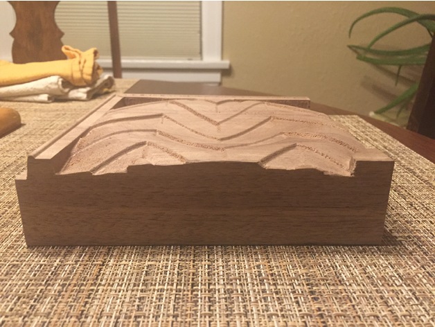
Walnut Block Tesselation 3D Print Model
Summary
.stl for design that was cut out of a block of walnut using a CNC Mill. Pattern was created with images and gradients in Affinity Photo. -
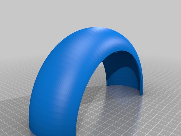
3d printed led night lamp Remix 3D Print Model
Summary
As the auther pointed out the parts dont fit together without shaving off some material.
I tried to fix it in 3d builder, just placing the parts together and the extracing excess from the parts.
There are a very thin line of material that should be removed on the bottom parts, but since its so thin my Slic3r doesnt care about it anyway..
I have not test printed it yet. -
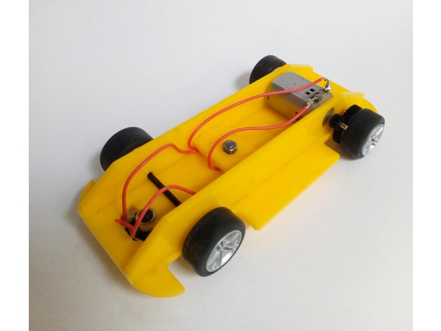
Scalextric chassis with transverse motor rear wheel drive 3D Print Model
Summary
scalextric chassis using the alternative gears to produce a transverse motor position. This set up will allow for shorter chassis to be built if required but you are set on the width.Standards
NGSS
Overview and Background
trying out some simpler versions of the 90 deg drive system for a year 7/8 club and came up with this.
Lesson Plan and Activity
no lesson plan included
Materials Needed
acrylic
4mm bolt
scalextric parts pack -
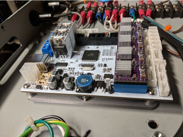
Mounting plate for a GT2560 Melzi board. 3D Print Model
Summary
Simple standoff mount for a GT2560 Melzi board.
The 2 mounting holes in the center are designed for 4mm screws.
Standoffs are designed to be tapped with 3mm threads.
The specific board is here :https://www.amazon.com/gp/product/B074TZC27M/ref=oh_aui_detailpage_o04_s00?ie=UTF8&psc=1
Print Settings
Printer Brand:
Creality
Printer:
CR-10
Rafts:
No
Supports:
No
Resolution:
.2
Infill:
20%
Notes:
Hatchbox silver PLA @ 200°C.
How I Designed This
Tapped standoffs with 3mm tap – holes are printed at 2.6mm. Mounting holes are 4.2mm, designed for 4mm screws. -
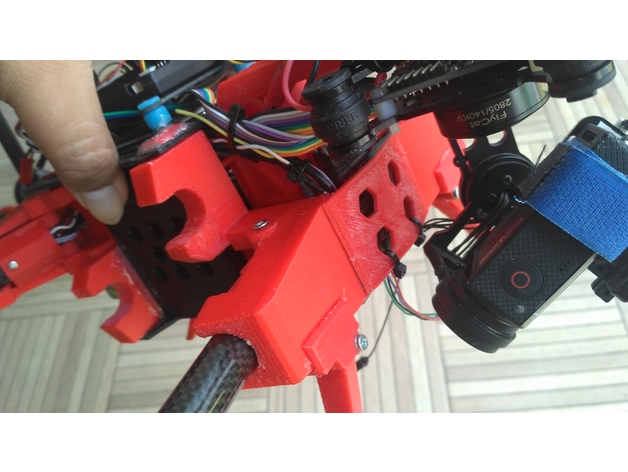
Fatboy front block 3D Print Model
Summary
This block use for enforce voltus (fatboy) frame front arm -
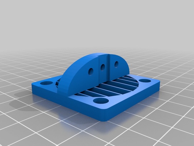
40mm fan bltouch mount 3D Print Model
Summary
just added fan guards, and rounded the corners a little is all -
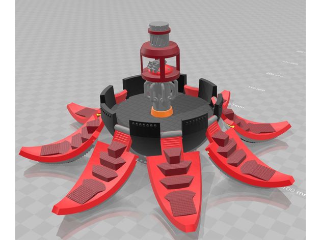
Drop Pod RT Era (28mm) 3D Print Model
Summary
Basic drop pod, recreated as best I could remember with some more modern attachments. Doors should be able to be opened and closed once assembled but a little filing might help.
Enjoy!
As always, please give feedback and/or requests. -
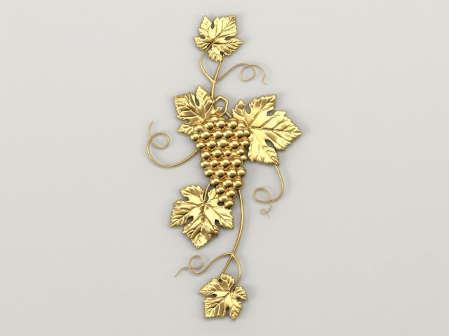
Bunch of grapes 3D Model
Оriginal size 116mm * 225mm *7mmModel for milling on a cnc machine. Suitable for decoration on the doors of kitchen furniture.
-
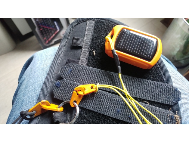
Croc fendu (sister clip) 3D Print Model
Summary
Croc fendu pour sécuriser ses accessoires rapidement. -
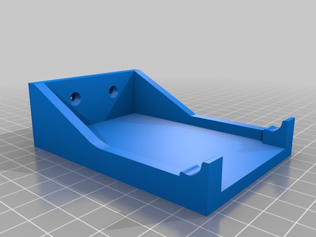
AA Battery Dispenser Wall Mount 3D Print Model
Summary
Wall-mount for LarNIL’s AA battery dispenser.
I added a small step in front of the dispenser to hold the batteries in place.
Print Settings
Printer:
Anet A8
Rafts:
Doesn’t Matter
Supports:
Doesn’t Matter
Resolution:
0.2 mm
Infill:
20-30% -
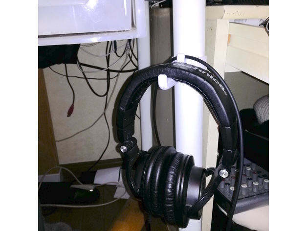
Headphone hook for 40mm pipe 3D Print Model
Summary
I use this by attaching it to IKEA’s ADILS.https://www.ikea.com/jp/ja/catalog/products/00353742/
This requires M3, 10 mm screws and nuts.
Print Settings
Printer:
Snapmaker
Rafts:
Yes
Supports:
Yes
Resolution:
0.15mm
Infill:
8% -
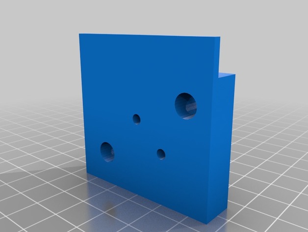
35nmm to 9mm film splitter 3D Print Model
Summary
I make this to cut 35mm film into 9mm film for my old spy cameras. -
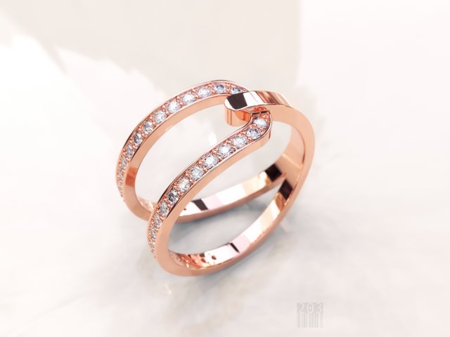
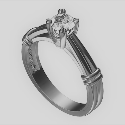
Womens diamond ring 3D Model
The model can be used for production, for casting and machining.STL model is ready for prototyping on CNC and 3D PrintingHigh quality modelweight in gold 3.400 gramweight in gold silver 2.300 gram
-
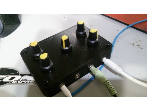
Mini Passive Mixer 3D Print Model
Summary
Plans and more details here : http://therandomlab.blogspot.com/2015/05/simple-passive-monostereo-to-stereo.html
This one does not match the schematic exactly. It has two stereo channels and one mono channel into one stereo out. Used 10K potentiometer, 1K resistors, and 1uF Capacitors. -
Terminator Pop Buddha 3D Print Model
Summary
Didn’t see a Terminator Pop Buddha statue. I combined Geoffro’s T-800 head and Buddha statue.
I though meditating on a pile of human skulls was more appropriate than the original base.
I used multiple skull models for the pile.
I don’t have a 3d printer yet, so I would appreciate any feedback from people who give it a shot. I’ve cleared any problems Meshmixer and loaded it up into Cura to look at the layers for anything obvious.
These skull base uses the following models:
Female skull injured by sword
Provinciaal depot voor archeologie Noord-Hollandhttps://sketchfab.com/models/be61ad2567024febbc1b9cc566a1d372#
Cranium
UNCG Imaging Labhttps://sketchfab.com/models/c39855833ff74943a2847972c9ff8700
kobanian skull (800 BC)
kantemratihttps://sketchfab.com/models/1d32fa630aeb46988f75c397df3cc429
There are a few more skulls I still need to add attributions for. -
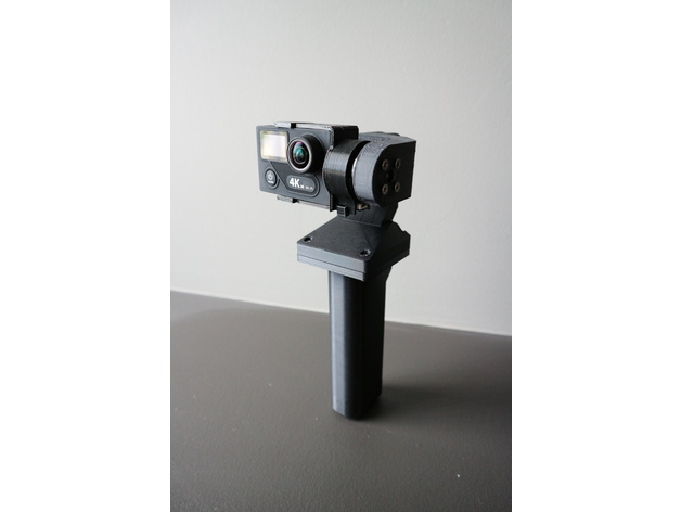
YAPM Handheld Brushless Gimbal 3D Print Model
Summary
Yet Another Poor Man’s Handheld Brushless Gimbal
Ever since I got the Mavic pro i haven’t been using my home built drones for aerial photography anymore. So I figure I’ll turn my cheap chinese 2 axis brushless gimbal into a handheld one so i can use it when i go traveling.
I’ve looked at the other designs on thingiverse but i didn’t like that they all left wires hanging about in the open. No offence to the other designers… I wanted one that would look much cleaner and travel better without having to worry about wires snagging on stuff. So I set out to design my own.
I designed this to be used with an EKEN H8 Plus and action cam with the same body format as Gopro Hero 3.
This design makes use of contact adhesive to glue the parts together and requires soldering and basic electronics skills. Some filing and fitting of the parts may be required. Do not attempt if you have a problem with any of the above.
Print Settings
Printer Brand:
Prusa
Printer:
i3 MK3
Rafts:
No
Supports:
Yes
Resolution:
.20
Notes:
Infill doesn’t matter as most of the parts are “thin wall” so most slicers would automatically do 100% fill anyways.
I printed this in PLA and the parts fit quite nicely. Where it’s too tight i used a file or sand paper to open it up a little. if printing in ABS it will shrink and make it too tight for the motors to move freely, so scale it up appropriately. I haven’t printed this in ABS so i can’t say how much to scale up.
Post-Printing
0. Required parts
Printed parts
No name chinese 2 axis gimbal like this one https://goo.gl/GvutmB
Mini rocker switch like this one https://goo.gl/tPpHTY
RC radio battery like this one https://goo.gl/znMdYC
JST connectors like these https://goo.gl/r9qnca
4 M3 x 14mm bolts and nuts, i recommend just getting a box of assorted ones like these https://goo.gl/eiZ4qW
Heat shrink tubing to fit over the legs on the power switch
Contact adhesive to glue PLA parts together
1. Disassemble the aluminium gimbal
Disassemble the aluminium 2 axis gimbal.
Remove all the header pins and the JST power connector on the control board.
I chose to eliminate header pins to make it more compact, the motor wires will need to be direct soldered to the pads during assembly. Make note of which wire connects where if necessary.
2. Remove support material
Remove support material from the parts. The support material inside the wire ways is a pain to remove; some spit grit and good ol’ elbow grease may be needed here.
It may be possible to print the motor arms without supports, but that will depend on your particular printer’s abilities with overhangs. i opted to go through the work of removing support just to make sure everything comes out right.
Take this time to ream out all the bolt holes with a drill bit.
3. Glue parts together
Apply contact adhesive to flat flared part of the part named “handle” and glue it to the flat side of the part named “bottom case”. Try to get the back edge to line up and left right centered on the bottom case. I measured the distance on each side and marked the position by scoring with an exacto blade to help me position the handle.
Take the part named “top case” and the part named “roll motor”. Use a file and an exacto blade to get the mating surfaces free of residual support material and as flat as possible. Apply contact adhesive to the indent in the top case around the opening and glue the “roll motor” part to the top case.
Take the parts collectively named “camera mount” and glue the two larger parts together. refer to the pictures to see how it’s supposed to go together.
The little “M” shaped clip is to hold the IMU sensor in place and will be needed during assembly.
Set aside and allow adhesive to cure.
4. Mounting the motors
Take the IMU sensor liberated from the aluminium gimbal and disconnect the cable on both ends. Feed the cable through the wireway in the part named “pitch motor”.
Take one of the brushless motor that was liberated from your aluminium gimbal, feed the motor wires through the part named “pitch motor” from the opening with the 4 hole bolt pattern and mount the motor with the 4 M3 screws that came with the original gimbal. You may choose to use other bolts, but be careful not to choose ones that are too long as it will damage the motor windings.
The parts was designed such that where the wires comes out of the motor points directly down the wireway. There is a gap between the motor and the edge of the opening on the inside face of the arm to accommodate free movement of the IMU sensor cable.
Now take the “pitch motor” assembly and feed the motor and IMU sensor wire through the gap between where the other motor goes on the “roll motor” part and then down the wireway and through the opening in the top case.
Take the other brushless motor and feed the motor wire down through the wireway the same as the other wires and mount the motor onto the part named “roll motor”. Also mount the pitch motor assembly to the roll motor.
Rotate the assembly throughout its range to ensure there is enough free play such that the wires are not strained from the movement. I used tweezers to reach in and pull some wire back into the wireways so that there’s some slack to allow for free movement.
5. Wiring it up
At this time the control board should be relieved of its header pins and power connector.
Solder a JST female connector to the mini rocker switch in series on the negative (black) side of the wire. Put some heat shrink tubing over the legs on the switch to give it some protection. Now feed the wires coming from the switch through the switch opening on the handle and snap the switch into place. bring the wires to be soldered onto the control board up through the bottom case opening and solder them to the control board.
Observe correct polarity as there is no diode protection on these boards. A mistake here could let out the magic smoke and render the board defunct.
Now take the top case/roll motor/pitch motor assembly. There should be 3 sets of wires dangling down from the top case wireway opening as follows
IMU sensor cable
Roll motor wires
Pitch motor wires
Cut the connectors off the motor wires, strip the wires and solder onto the corresponding solder pads on the control board as noted in step one during disassembly.
6. Affix the IMU sensor, camera mount
Place the IMU sensor into the slot on the camera mount and install the “M” shaped clip. The IMU sensor should be affixed into place. Run the IMU sensor cable along the space around the motor and connect to the IMU sensor. Mount the camera mount onto the pitch motor with the 3 screws that came with the original gimbal.
Rotate the camera mount assembly 180 degrees and ensure there is enough slack in the IMU sensor cable to allow for free movement.
Connect the other end of the IMU sensor cable to the control board.
7. Apply power and test
As i didn’t design an opening to allow for USB connection for PID tuning, at this point i recommend connecting the battery and testing before final assembly.
Just like tuning the gimbal on a drone, the action cam should be installed in the camera mount for weight balance.
8. Case closed
Use 4 M3 x 14mm bolts and nuts to assemble the top case and bottom case assembly together with the control board in between. The top case was designed with enough space to hide all the wires inside without pinching them, but do be careful not to pinch any in between the bolt posts.
Now the gimbal should be ready for action. Connect the battery and shove it up the handle, shove the extra wires and connects from the battery in the free space around the battery. Snap in the pommel cap. The positioning tabs on the cap may need to be filed down a bit for an easier fit.
Enjoy. -
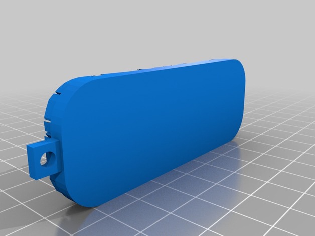
Keychain 3D Print Model
Summary
customizable keychainStandards
NGSS
Overview and Background
Lesson Plan and Activity
no lesson plan
Materials Needed
3d printer -
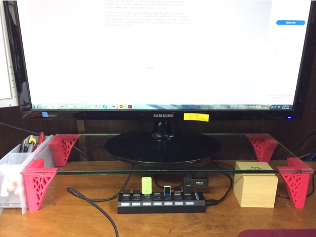
Monitor Stand 3D Print Model
Summary
You can print the center leg to support the monitor stand in case it is long.
Print Settings
Printer Brand:
Prusa
Printer:
i3 MK3
Rafts:
Doesn’t Matter
Supports:
No
Resolution:
0.15
Infill:
20 -
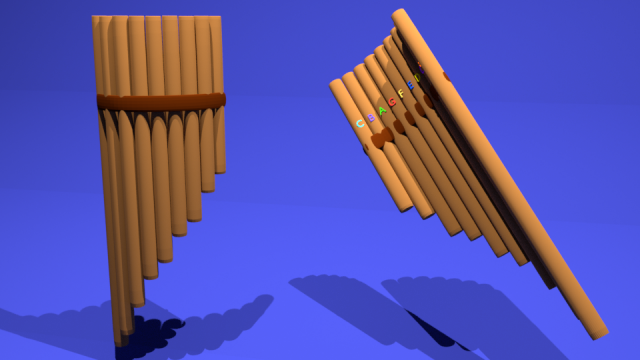
Pan Flute 3D Model
Hey,Made this Pan Flute and it should be in tune I’m open to all feedback thanks a bunch :)”I designed this cool model using SelfCAD software. I just discovered this CAD program recently and it’s really cool. You can model, sculpt and print all under one program and the Slicer is also part of the program.Can be self-taught in just under 5 hours!, Check it out here too https://www.selfcad.com.”If you have any questions feel free to ask!
-
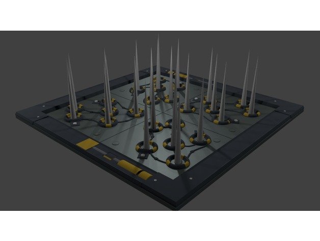
Fortnite Working Spike Wall 3D Model
Hey,Hope you guys like this Spike wall from Fortnite. if you want the working version use the floor without spikes and separately print the extendable spike. they are telescoping spikes to put the small first and step up one larger. DO NOT PUT ON THE FLOOR. If you hurt yourself or anyone else that’s your fault YOU HAVE BEEN WARNED. BE VERY CAREFUL!!!If you have any questions feel free to send me a message ;)https://www.epicgames.com/fortnite/en-US/buy-now/battle-royale
-

Wreat 3D Model
3D model is an wreath for visualization and production on CNC machines.Model for 3D printing.Size of model in mm: 35x29x0.5mmAvailable formats are .c4d, .obj, .fbx, .ma/.mb, .lwo/.lws, .3ds, .3dm, .dxf/.dwg, .stl.Download 3D model an wreath .obj, .stl, from VitAnGen
-
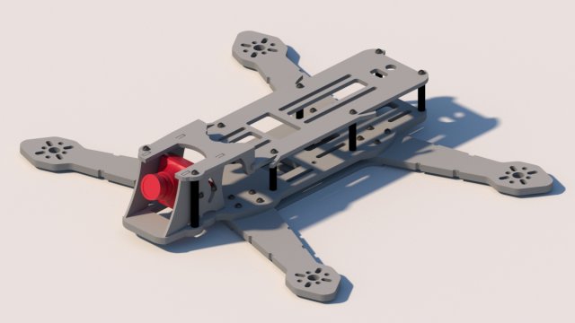
Frame Race Drone FPV 250 mm 3D Model
What’s in the set :1 x Top plate 2.5 mm1 x Lower center Plate 4 mm1 x Lower plate 1.5 mm1 x Arm1 x Bumper 2.5 mm1 x Side camera plateRequired metal parts to twist the frame :2x Spacer M3x30mm6x Spacer M3x20mm16x M3x6mm Screws16x M3x10mm Screws
-
Discone Antenna Hub 400MHz and up, 70cms, ADS-B 3D Print Model
Summary
The Discone antenna is remarkable in that it is capable of receiving and transmitting over a wide range of frequencies with good matching. Because of this, it is a good match for SDR receivers such as the popular RTL-SDR sticks.
The only really tricking thing about making a discone is that the disc has to be balanced at the very top of the cone, which is mechanically awkward.
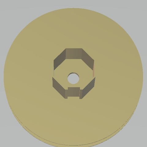
The two parts here allow the cone to be solidly clamped and provide an adequate base for the disk. There also two holes for bring the coax centre and braid out to the disc and cone.
The base part has a socket at the bottom for 25mm (1 inch) plastic conduit for mounting
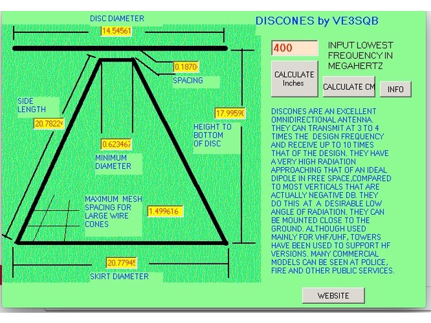
This antenna illustrated is designed for 400MHz and up, and as such transmits well on the 70cms amateur band, US and UK PMR channels and 23cms. It also receives aircraft ADS-B signals very well. I used .3mm plastic sheet for the cone and 2mm plastic for the disc, and then covered them with aluminium weatherproof tape. Be sure to check for continuity across the tape stripes.
The screenshot is of a calculator by VE3SQB which can be downloaded from http://www.ve3sqb.com/ if you want to make attenna’s for other ranges. -
CR-10S Hinged Filament Sensor Mount (Bottom Plug) 3D Print Model
Summary
CR-10S Hinged Filament Sensor Mount (Front Plug)https://www.thingiverse.com/thing:2791872
CR-10S Hinged Filament Sensor Mount (Bottom Plug)https://www.thingiverse.com/thing:2826099
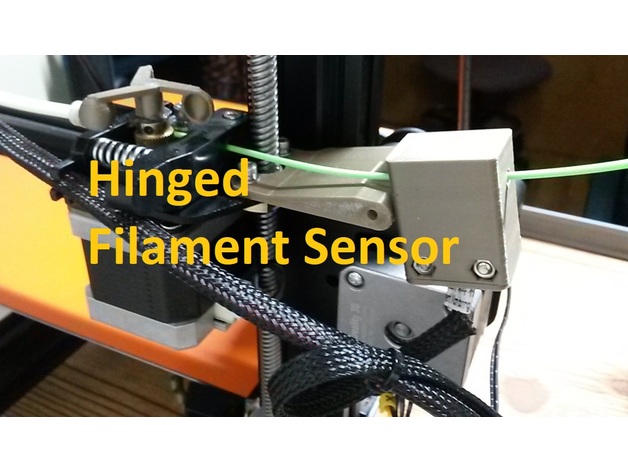
Lets be honest. The filament runout sensor is a great addition to the Creality CR-10S, but the factory slide-on mount that Creality supplies sucks. I download and printed several other designs from here and just wasn’t happy with the alignment or functionally of them, so I designed my own.
I wanted the filament to be feed straight thru with enough room inbetween to manage any kinks or wobbles in the filament with your hands. I also wanted a better way to reduce friction thru it when near Z=0 and Z = 200+ as the filament is drug thru the horizontal position of the sensor first which is dependent on the way you install the roll (over the top or under). Thats when putting a hinge inbetween seemed like the perfect solution as I run a TUSH spool holder with the extruder feed off the bottom of the spool. I designed this Hinged Filament Sensor Mount so it can be bolted onto the Z-axis brass lead screw nut using factory hardware, then the mount is stabilized to the Z column roller mount right at the hinge. I also designed it so you could run the sensor fully enclosed or with the printed cap to keep crud out. You will need (2) M3X20 screws with (2) M3 hex nuts. Hinge is printed in place.
Please note that after printing you will need to carefully twist the built-in support material off in the same direction as the pivoting hinge. If you use flush cutter on the support material, you may end up splitting the mount in half. The hinge for this design requires a M3 x 30mm LG screw and a M3 Nut as I couldn’t model it assemblied without alot of wasted support material.
The sensor I designed this around can be purchased here:https://macewen3d.com/products/cr-10-cr-10-s4-and-s5-replacement-endstop-limit-switch
Which is the same as the factory Creality CR-10S filament runout sensor or Axis stop sensors. My machine actually came with a spare, which made designing/refining it pretty easy.
Some people didn’t like my previous version of this mount since the plug for the sensor was in front, so I remixed it so the plug is now facing downward. -

Golf Ball Belt Clip Remix 3D Print Model
Summary
This is a remix from the TheKre8Group’s one.
Added 3 tee holders, and a slot to label/mark the balls (putting helper).
Printing tips:
o.2 layer height
perimeter width : 0.45
and allow single extrusion wall for the outer perimeters (that’s for the support wall).
All attribution to TheKre8Group! -
Triangular Sinusoidal Vase 3D Print Model
Summary
I’ve got a little overhang on one face but it is still a nice print ! -
Earring 3D Model
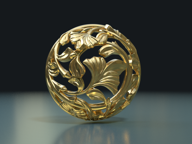
Print ready earring.Measure units are meters.The model is 1.5 cm in diameter.It has no clasp so you can decide what type of it you need and order it separately.Two versions of the earring are available:1) With cylinders. This Cylinders can be used to fix little gems.2) Without cylinders.Available formats: .blend, .fbx, .obj, .dae, .3ds, .stl.
-
Christian cross 3D Model
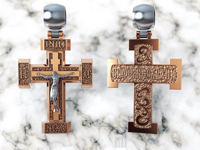
The model can be used for production, for casting and machining.STL model is ready for prototyping on CNC and 3D PrintingHigh quality modelweight in gold 61,00 gramweight in gold silver 41,400 gramin archive there is file easier
-
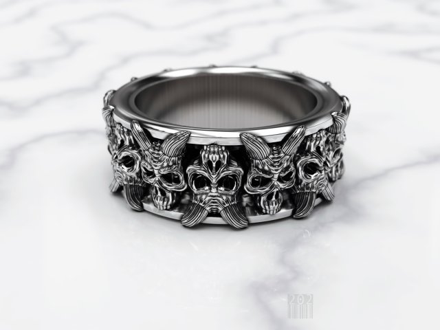
Skull ring 3D Model
The model can be used for production, for casting and machining.STL model is ready for prototyping on CNC and 3D PrintingHigh quality modelweight in gold 23.300 gramweight in gold silver 15.600 gramthe design was developed by me
-
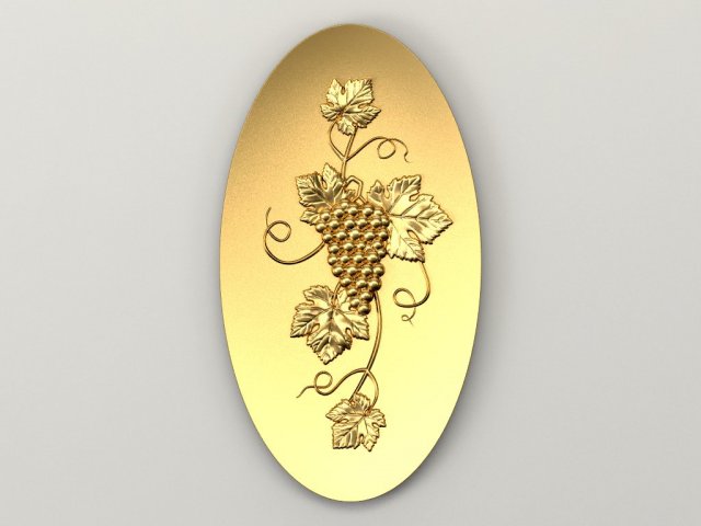
Bunch of grapes Concave oval 3D Model
Оriginal size 160mm * 190mm * 10mmModel for milling on a cnc machine. Suitable for decoration on the doors of kitchen furniture. Decor in the recessed oval.
-
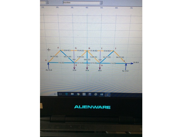
3D Printed Bridge 3D Print Model
Summary
This is a 3D printed bridge that can support over 100 times its own weight. The members in the still file section above this description are printed as follows: Members 1 and 3=100% infill, members 2 and 4=30% infill. The load to weight ratio of this bridge is a whopping 137! The members can be slightly fragile at the points of connections, and for this reason the individual stl filedps for each member are included for piece by piece printing. -
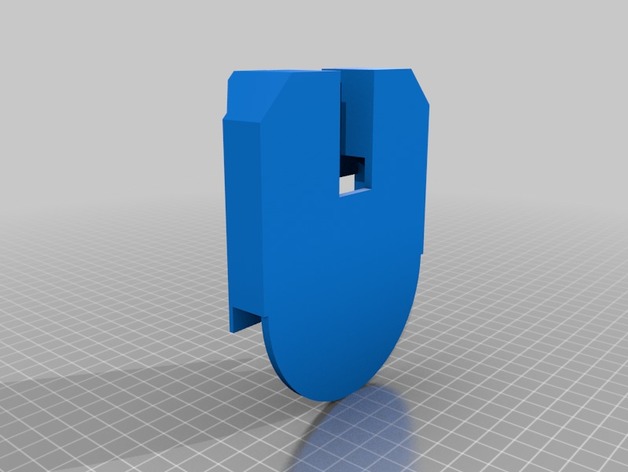
Wallmounted S8 Wireless Charger 3D Print Model
Summary
Holds naked S8 and a 95mm dia/10mm thick wireless fast charger. Use VHB tape along edge of wireless charger to fix to the mount and use 3M strips to fix to wall. -
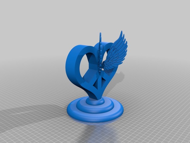
Veronica’s Heart 3D Print Model
Summary
Ever since my daughter was little she loved drawing peace signs and hearts with wings. She really wanted me to print her a peace sign and we really couldn’t find one we liked so I made this.
Print Settings
Printer Brand:
Creality
Printer:
CR-10
Rafts:
Doesn’t Matter
Supports:
Yes
Resolution:
.2
Infill:
15How I Designed This
-
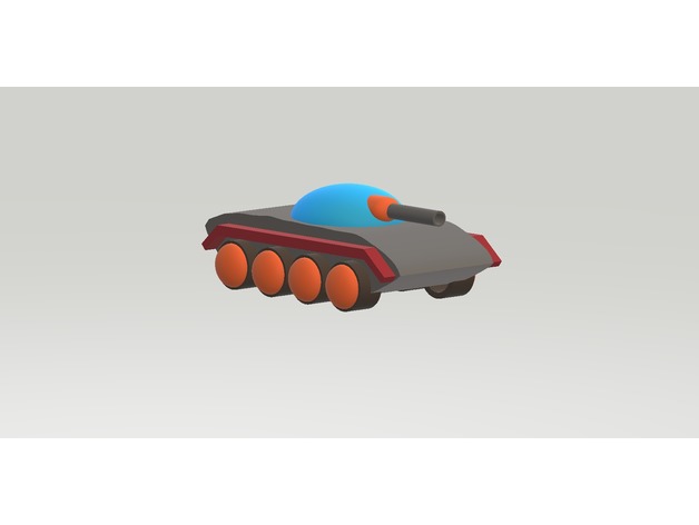
Wheel tank 3D Print Model
Summary
This a kind of 8 wheels Tank.
I think a good tank require: Speed, armor, and fire power.
Transport capacity must also be available.Overview and Background
Introduction
I design this by Paint 3D, 3D builder.
I build tank scale model for fun.
I have some idea to improve a tank, and try make it more reasonable and Universal. -
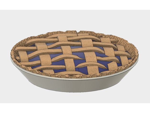
Pie 3D Print Model
Summary
Pie designed for either a single color printer (Whole Pie.stl) or for multi-color printers with the other parts. This is a work in progress, and will likely receive some tweaks.
You will likely need to print it at a reduced size – the actual file is 254mm in diameter. -
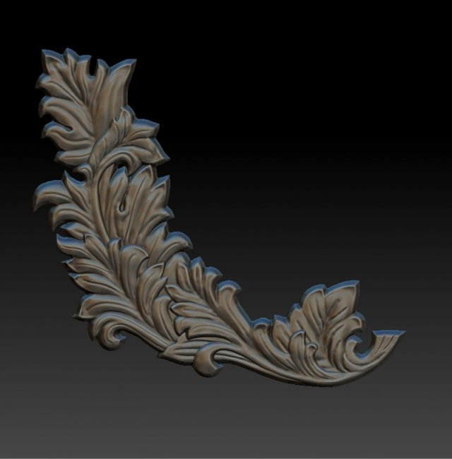
Branch 3D Model
3D model branch for visualization and production on CNC machines.Model for 3D printing.Available formats upon request: .c4d, .obj, .fbx, .ma/.mb, .lwo/.lws, .3ds, .3dm, .dxf/.dwg, .stl.Download 3D Model branch obj. stl by VitAnGenAvailable formats upon request: .c4d, .obj, .fbx, .ma/.mb, .lwo/.lws, .3ds, .3dm, .dxf/.dwg, .stl.Завантажити 3D Модель branch .obj, .stl by VitAnGen
-

Original pen holder 3D Model
Stand under the handle of the original form. This is a square spiral twisted. At the top there are four holes for pens or pencils. Pen holderStrict and solid appearance