Summary
This adapts the https://www.thingiverse.com/thing:1161013 to a CTC prusa
Tag: CTC
-
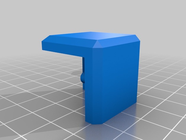
CTC Prusa i3 fan adapter 3D Print Model
-
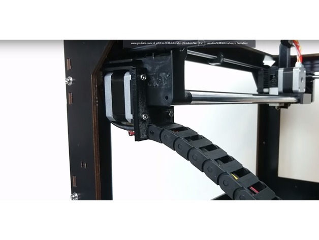
CTC PRUSA i3 Pro B Bowden Drive with Autoleveling 3D Print Model
Summary
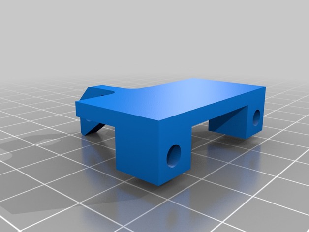
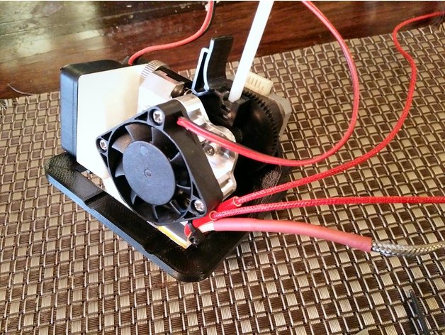
My CTC hotend broke and I was without a 3D printer. Luckily I am in the process of building a HEVO and therefore I had the mount, hotend, extruder, retainer and duct already on hand. By drilling two extra holes and removing a little plastic near the X endstop flag in the mount, I made it fit the CTC carriage perfectly. Again, since my printer was down, I didn’t design this in CAD and just modified the piece I had by hand and then created the STL for thingiverse so no guarantees that it will fit. I left a bridge in there for support that you will have to break out and I put in two mounting options; one way the way I mounted it by drilling holes, and another for mounting it with M3 brass fittings to lower the mount closer to the bed. The HEVO mount has the proximity probe spot already, so I figured I should add that sensor as well.
If you are ready for a double mod, keep reading…
Items Needed:
Soldering Iron
several connectors
connector wires (from breadboard)
Arduino IDE
an extra Arduino as ISP to update the bootloader on the CTC Aduino
Marlin firmware
BOM:1 x 5V NPN M12 inductive sensorhttps://www.aliexpress.com/item/M12-4mm-detection-5VDC-NPN-NO-LJ12A3-4-Z-BX-5V-cylinder-inductive-proximity-sensor-switch/32553311139.html?spm=2114.13010608.0.0.iDrnoz
3D Printer Accessories V6 J-Head Hotend RepRap Extruder for 1.75mm Filament, Direct Feed or Bowden. w/ 0.4mm Nozzle, 12V fan, and 3ft PTFE Bowden Tube
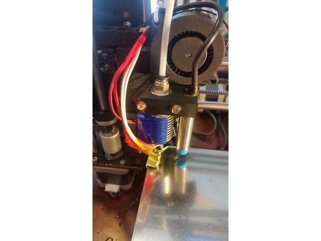
ALPTAhttp://a.co/9PxYSl48.5″ x 8.5″ galvanized 28ga metal plate to place between the hotbed and glass plate. This ensures that the sensor is triggered properly. Without it you will need to either not use glass or you are going to be very close to the nozzle level. Ferrous metals are the best at triggering proximity sensors, that’s why I didn’t use aluminium.
8.5″ x 8.5″ x 0.880″ glass plate. I prefer to print on glass.
Extruder of your choice (e.g. find one on thingiverse)
ProcessPrepare and install your material for your heat bed. Cut the galvanized plate with some metal shears to size. IMPORTANT: make sure the metal does not short out any contacts on the heated bed. You need to cut around those areas!.
Get the glass plate from your a hardware store. They will cut it to size if you ask nicely. You need the corners angled to have room for the screw heads.
Prepare and install the J hotend and proximity sensor with the extruder mount, retainer and duct from the HEVO project.
Solder the 5V and Ground connections to the board. I chose to use add a connector for easy disconnect.
Make a backup of the original settings. These were mine:
15:07:46.286 : echo:Hardcoded Default Settings Loaded
15:07:46.286 : echo:Steps per unit:
15:07:46.287 : echo: M92 X78.74 Y78.74 Z2560.00 E105.00
15:07:46.287 : echo:Maximum feedrates (mm/s):
15:07:46.287 : echo: M203 X400.00 Y400.00 Z2.00 E45.00
15:07:46.287 : echo:Maximum Acceleration (mm/s2):
15:07:46.287 : echo: M201 X1400 Y1400 Z100 E80000
15:07:46.287 : echo:Acceleration: S=acceleration, T=retract acceleration
15:07:46.287 : echo: M204 S1400.00 T5000.00
15:07:46.287 : echo:Advanced variables: S=Min feedrate (mm/s), T=Min travel feedrate (mm/s), B=minimum segment time (ms), X=maximum XY jerk (mm/s), Z=maximum Z jerk (mm/s), E=maximum E jerk (mm/s)
15:07:46.287 : echo: M205 S0.00 T0.00 B20000 X13.50 Z0.30 E5.00
15:07:46.287 : echo:Home offset (mm):
15:07:46.287 : echo: M206 X0.00 Y0.00 Z0.00
15:07:46.287 : echo:PID settings:
15:07:46.287 : echo: M301 P19.86 I1.00 D98.93Upgrade your bootloader. Here is how to do it:
Time to download, configure and install Marlin. Use the GEEETECH example in the examples folder as a base. I attached my Configuration.h file here for reference with auto leveling enabled: https://www.thingiverse.com/download:4494314 . Using this config will consume 94% of the memory. So there is hardly anything left for additional features.
Last but not least make sure you adjust the z-axis in the LCD until you get the nozzle in the correct location (mine was -0.25). Then make sure you save your settings.
*ANOTHER BENEFIT of UPGRADING YOUR FIRMWARE**
The CTC is over-extruding (at least mine was). In Cura I had set the correction in the start script, but with the new firmware I changed the E stepper from 105 to 95 in the configuration.h, so no more start code fix needed! -
Filament guide for Prusa Anet Geetech CTC printers 3D Print Model
Summary
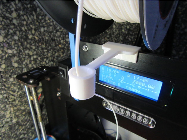
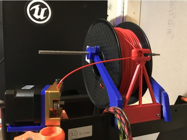
This is my version of filament guide based on this one:https://www.thingiverse.com/thing:1240326
A larger pipe will keep more straight the filament at the end of the reel, when the loops are smaller.
Suitable for printers:
Prusa
Anet
Geetech
CTC printers
…and many models with a frame 5mm width.
Feel free to adapt the files to your needs.
Thank you so much for you comments, like, download and collecting!
Print Settings
Printer Brand:
Prusa Printer:
Prusa Clone Rafts:
No Supports:
No Resolution:
0,2 Infill:
100% Notes:
For better results, use cooling fan. -
CTC Bizer Makerbot Replicator Dual to Single Titan Aero 3D Print Model
Summary
CTC Bizer Makerbot Replicator Dual to Single Titan Aero
Drop in Dual to Single Extruder Mod with Hotend Cooling duct.
Used original motor and just added E3D Titan with Aero Hotend.
Cooling duct uses M3 Knurl Insert Nut threads from ebay https://www.ebay.com.au/itm/122046120352 I used the M3x4x4 Knurl Insert Nut
You may need to trim one corner of you Aero Cooling Fan as per the images.
The bracket places the hotend nozzle almost exactly over the original Right Hand Nozzle placement to reduce firmware adjustment. Also has striker for the X carriage endstop.
You will need to measure and re drill to move the Z axis endstop up to compensate for the higher nozzle.
Print Settings
Printer:
Lulzbot TAZ6 Custom Rafts:
Doesn’t Matter Supports:
Yes Resolution:
0.3 Infill:
60 – 80% -
CTC Prusa Low friction spool holder 3D Print Model
Summary
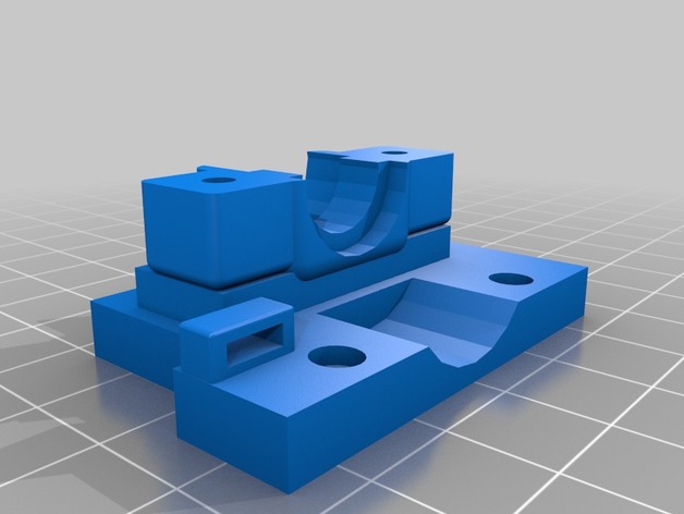
for CTC prusa i3 5mm plywood frame
resolution 0.3mm -
Snap-on CTC Dual bed levelling jig 3D Print Model
Summary
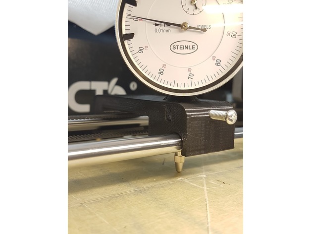
Designed from scratch using the layout and coarse dimensions from https://www.thingiverse.com/thing:2460482
OnShape link where you can edit to your custom specifications: https://cad.onshape.com/documents/28e0bcaa853c187d0624b81f/w/fd7acef5713bafce038c5cfe/e/7e7969d14473af0ccc5dd0ed
Improvements:
snaps on instead of using magnets or other means
wider base for improved stability
longer support for the indicator shaft
offset on top to allow clearance for the indicator dial
Instructions: printed laying on one side, PLA, infill 15%, no raft or support. The indicator shaft will deform a bit while printing, hence why it’s oversized.
Design notes:
Distance between rails is 70mm, rail diameter is 8mm, indicator shaft diameter is also 8mm. All holes have been oversized to 8.5-8.7mm, this is both to allow for printer tolerances and to make it easier to slide the “carriage”. You can edit the first two sketches to reduce the oversize, if you want a tighter setup.
I currently have about 0.05mm slop/play with this setup, but my bed is warped almost 0.2mm, so the jig play doesn’t affect the readings so much.
The chamfer on top is ugly but allows for better printing without supports.
The snap-on distance is 0.7mm. You can increase it if you want a tighter fit, decrease it if the required force to snap is too high.
Post-printing:
The indicator should be a tight fit (“good enough”) but there is a hole for an M4 screw that’s designed to be tapped. There’s also an M4 nut retainer, if you don’t want to tap the hole. You can also probably just drive the screw in, without tapping, -
CTC Filament Guide 3D Print Model
Summary
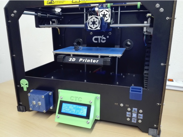
This is a simple filament guide. This can be placed in front of the spool in order to keep the process simple.
Print Settings
Printer:
CTC Prusa I3 Rafts:
No Supports:
Yes Resolution:
.3mm Infill:
50% -
CTC Display Mount 3D Print Model
Summary
I searched for an angled display holder for my CTC printer, but found nothing useful!
The only one I like a bit: https://www.thingiverse.com/thing:2057624
So I reworked this according to my ideas 🙂
Print Settings
Printer:
CTC printer with dual extruder Rafts:
Yes Supports:
Yes Resolution:
0,1mm Infill:
30% Notes:
The raft is absolutely necessary, otherwise the supports does not hold on the base plate!!! -
CTC Prusa i3 Pro B (E3D V6 Mount w/ Radial Fan mount) 3D Print Model
Summary
Created using TinkerCAD.
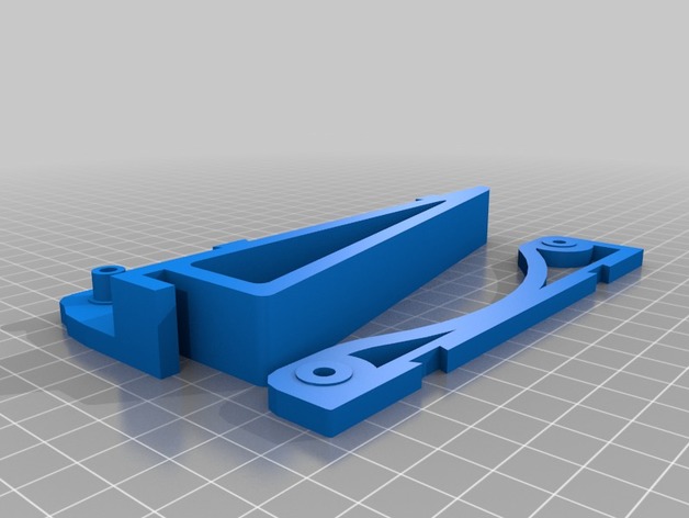
This mount was created to allow a 40mm radial fan to be attached to the front of the mount. The mount connects to the original carriage. It allows for a zip tie to be placed in order to hold all wiring.
Print Settings
Printer:
CTC Prusa I3 Rafts:
No Supports:
Yes Resolution:
.3mm Infill:
60% Notes:
Rotate top 180 degrees for the print.