Summary
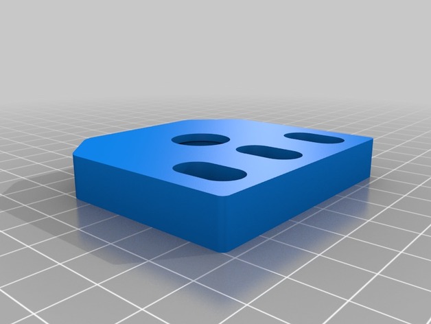
Have some left over M8 all-thread after upgrading to lead screws? This might be the perfect up-cycle option for them
Print Settings
Printer:
Geeetech i3Pro B
Rafts:
Doesn’t Matter
Supports:
No
Resolution:
.2
Infill:
30
Tag: z
-
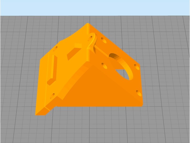
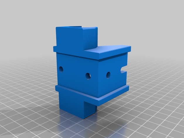
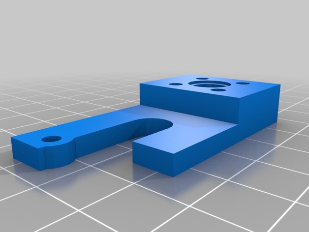
Geeetech i3 Pro B Top Z Bracket with M8 Support. 3D Print Model
-
TronXY X3 Z Axis Motor 3D Print Model
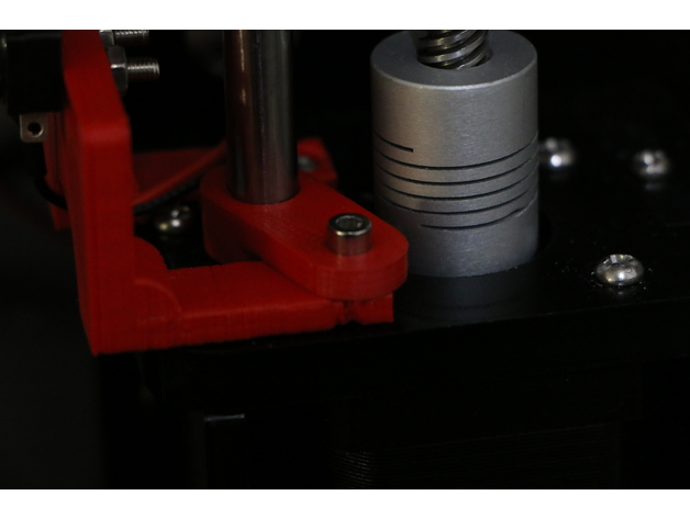
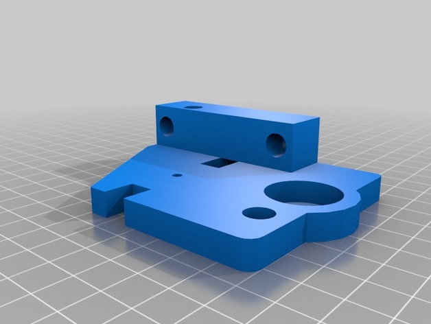
Summary
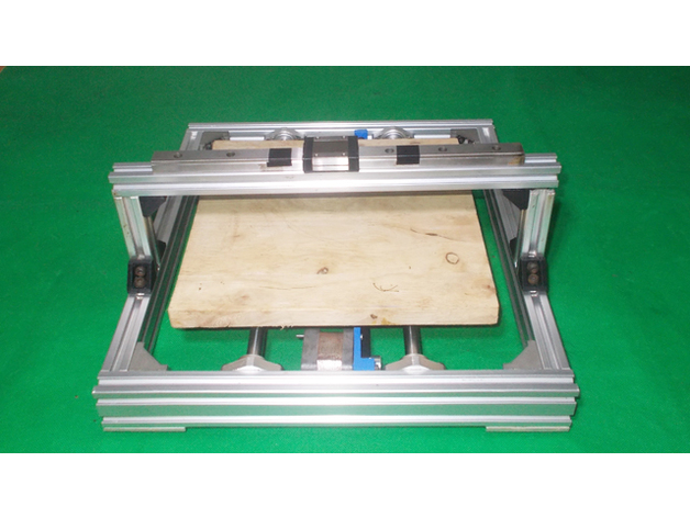
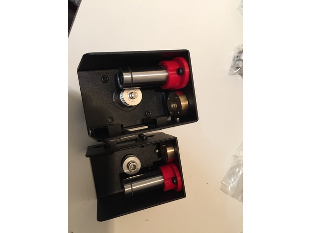
the first time i built my printer, i hated how much unnecessary time i spent puting the Z motors.. everything was loose or not in perfect alignment. Then i found Lexa’s one and i loved it, except for one thing.. i had to screw the piece first and then the motor, which for me, was troublesome or unconfortable, so I created this piece which has the scew holes outside, so.. if you t-nut wasnt placed correctly you can fix it without too much trouble.
TL;DR; the screw holes are outside from the motor case so you can put the motor or the screws in whatever order you want.
YOU WILL NEED:
3x m4 screws (i used only the 2 from the original ones, one on top and one on the side)
3x m4 nuts (t-nut or else)
Print Settings
Printer:
Ttronxy x3
Rafts:
Doesn’t Matter
Supports:
No
Resolution:
0.2
Infill:
20%
Notes:
im so sorry, but the ideal print way is as in the first picture and, ideally, with a fan, since i kept modifying the file, i found it was better to just fix the position in the slicer rather than in Fusion 360 -
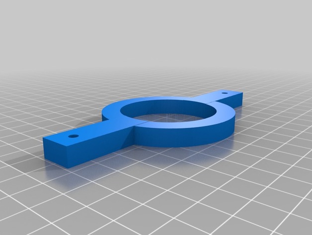
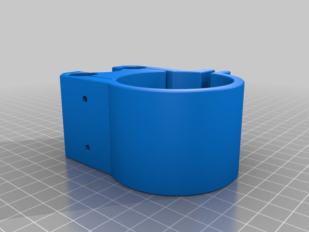
Z axis strap for Maslow 3D Print Model
Summary
I saw a picture on a Maslow forum where someone created one of these straps and used some bungee cords to keep a little tension on the z axis motor so that the router didn’t jerk.
Get some two cheap bungee cords and you’re set. There are holes already in the strap.
You don’t need a big 3D printer. This will fit on a 4″ x 4″ printer at a diagonal. -

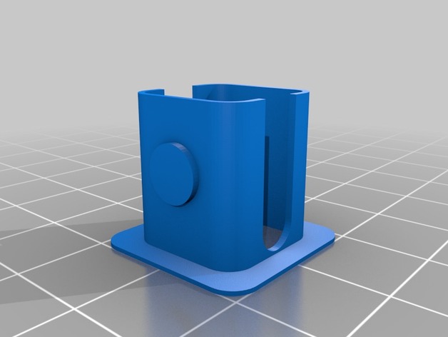
Removable Extruder Fan Holder A8 with Z probe 3D Print Model
Summary
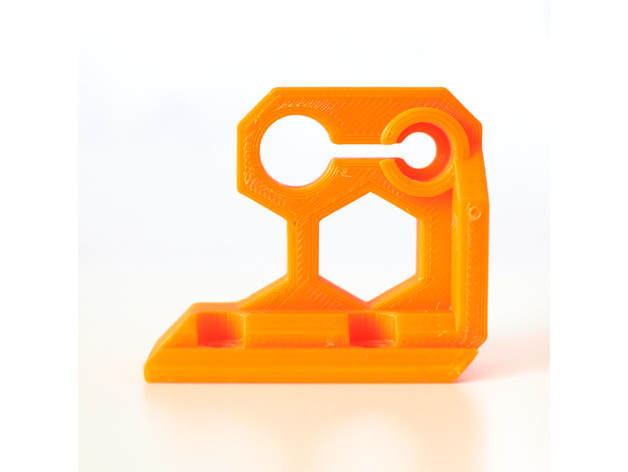
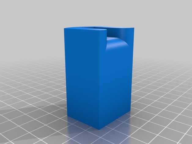
This design allows you to easily replace your filament by manually removing the extruder fan.
The extruder fan sits on on sliding slot, and to remove it you just need to pull it up.
I have add a Z-Probe ring if you have a sensor..
This is a remix from petiz ( https://www.thingiverse.com/thing:2822215 )
What you need to know:
print the design
remove the heatsink and fan cover
use the same two 50mm screws to put the mount in place
add the Z-Probe
simply slide the fan in!
Feel free for comments and photo if you make it
Print Settings
Printer:
Anet A8
Rafts:
Doesn’t Matter
Supports:
No
Infill:
15% – 20% -
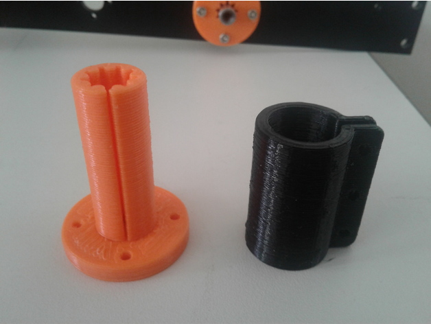
Tronxy X5s Z axis printed split bushing 3D Print Model
Summary
When building my Tronxy X5s, I was not impressed by the stock Z axis bearings. So I designed and printed a replacement system. The bushing has a split in it and you slide the sleeve over it and tighten it with 2 M3 screws and nuts. I printed the bushing in PLA and the Sleeve in PETG, but you could print it in PLA. There is also a short version in which a IGUS RJ4JP-01-08 sits on top of it and both are held and tightened by the sleeve. This was created for the people who do not like PLA bushings.
Print Settings
Printer:
SmartRap – Highly modifed
Rafts:
No
Supports:
No
Resolution:
.2
Infill:
30
Notes:
Set up the number of shells to be enough to create the bushing vertical section without any infill. Allowing the shells to make up the “fingers” of the inner part of the bushing. Mine was 3 shells.
How I Designed This
Designed in Fusion 360 -
tutor endstop z chasis acero 3D Print Model
Summary
facilita el acceso al endstop del eje z
Print Settings
Printer:
rojo 3d allmetal i3
How I Designed This
solidworks -
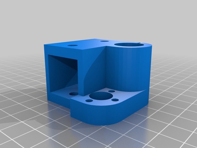
Maslow CNC Bosch POF 1200 AE Z Adjust Mount 3D Print Model
Summary
This is a motor mount and lead screw nut mount for the Bosch POF 1200 AE, using the Maslow CNC Z adjust motor to drive it.
The lead screw i used: http://bit.ly/2FzCfZK
The coupler i used: http://bit.ly/2EGimiv
Print Settings
Printer:
Anet A6 Rafts:
No Supports:
Yes Resolution:
0.3mm Infill:
10% Notes:
Print it how you like, its just there to stop the motor from turning and doesnt have to be THAT strong at all. -
AM8 Z Axis Single Bearing 3D Print Model
Summary
I’ve broke a few of these trying to slide it onto the 2020 v-slot extrusion. The back of it also rubs against the 2040 vertical extrusions. I removed some of the material from the inside to allow it to slide onto the 2020 easier and removed some from the back so it didn’t rub on the 2040 vertical extrusions.
Mirror the part for the opposite side.
Print Settings
Printer:
AM8 Rafts:
No Supports:
No Resolution:
.2 Infill:
80% -
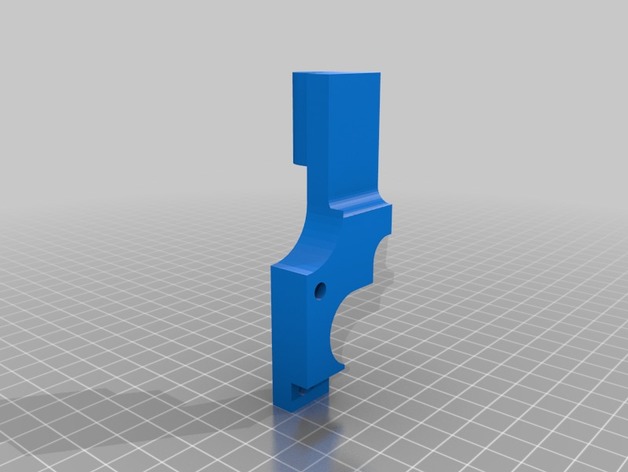
MPSM Fully Adjustable Z Spacer (MP Select Mini) 3D Print Model
Summary
Fully Adjustable Z Spacer
MP Select Mini
By Wiley Kyoto
This Z spacer is designed to give you continuous adjustment from 1mm to 5mm. If you want to switch between the stock bed and glass bed, you don’t have to adjust your print bed and then re-level it. If the beds already level, just adjust the spacer for the change in height to account for the glass thickness. Also If you change nozzles, the new one might be slightly longer or shorter, so just adjust the Z offset accordingly. I gave the Bracket a slight bend so it keeps constant pressure to hold it firmly in place.
My Print Setup:
PLA
210/60C
No Supports
0.175mm Layer Height
1.4mm Wall Thickness
1.05mm Top and Bottom Thickness
Orientation – Lay the AdjArm and Bracket flat on their sides. Put the AdjDial on one of the flat ends (I had numbers near the top).
Assembly:
Put the AdjDial on the Bracket, in the groove next to the indicator mark, with the numbers closest to the outside edge.
Insert the sloped edge of the AdjArm through the AdjDial, with the threads of the AdjArm facing away from the Bracket.
Keep pressure pushing the AdjArm into the AdjDial as you start to turn the AdjDial clockwise. Keeping in mind that the thread is reversed thread, such that turning the AdjDial clockwise will wind the AdjArm farther in.
Set the AdjDial to roughly the right spot (See Reading the Dial).
Make sure the head position of the printer is a good couple centimetres in the +Z direction, to prevent damage to the Z limit switch.
Insert the assembled spacer through the vertical slot in the back of the printer tower, snapping it into place on the Z Bearing Block(Black Plastic Block with metal rods running vertically through it), which you can see through the vertical slot. You should hear and feel a solid click as it snaps securely into place, pushing forward firmly on the top lever of the spacer should help it snap into place.
Make final adjustments the the AdjDial but homing the printer and checking the fit with a piece of paper under the nozzle.
Reading the Dial:
Note – the readings won’t have absolute accuracy as it depends on the exact placement of the Z Limit switch, but the relative accuracy should be great.
The AdjArm has 4 notches, with numbers 1 to 4 next to them. These represent whole mm steps.
The AdjDial has 40 notches, every 4 notches are numbered .0 through .9. These represent decimal mm steps. Each notch is a 0.025mm step.
The Bracket has one indicator notch which lines up with the notches on the AdjDial to indicate where to read the setting.
When the outside edge of the Bracket is lined up with the first notch(next to the 1) on the AdjArm and the .0 setting on the AdjDial is centred on the indicator notch, the spacer is set to 1.0mm.
When the AdjArm is all the way into the AdjDial, and the AdjDial is set to .0, the spacer is set to 5.0mm.
The spacer can be set less than 1mm but at some point (around 0.7mm on my printer) the limit switch will slip off the end of the spacer and effectively act as 0mm offset. -
cnc2417 Z axis 55mm spindle mount holder 3D Print Model
Summary
55mm Spindle mount for chinese CNC “cnc2417” 24 x 17cm . This router mount 35mm spindle as default and not compatible with more diameter.
Assembly requires:
2 x bolts M3 >18mm
2 x nuts M3
4 x screws M3 16mm
No material support needed
Print Settings
Printer:
HyperCube 3D Printer Rafts:
Doesn’t Matter Supports:
No Resolution:
0.2mm Infill:
100% Notes:
https://www.thingiverse.com/thing:1752766
How I Designed This
Designspark Mechanical Downloads:
De: https://www.rs-online.com/designspark/mechanical-software-de
En: https://www.rs-online.com/designspark/mechanical-softwareBuy
Cnc router CNC2417
https://www.aliexpress.com/item/cnc-2417-diy-cnc-engraving-machine-3axis-mini-Pcb-Pvc-Milling-Machine-Metal-Wood-Carving-machine/32799560097.html?spm=a2g0s.9042311.0.0.eAyshb -
Z Axis Bearing Holder 3D Print Model
Summary
Z Axis Bearing Holder 1.0 for 3030 profil
Print Settings
Rafts:
No Supports:
No Resolution:
0,2 Infill:
30-50 -
Cura Lift Head at Z for PETG Print Gap Plugin 3D Print Model
Summary
Well, they say that PETG likes to “lay down” and not be “smooshed down” like other filaments. After the first layer, you should raise the print head slightly so there’s a gap between the nozzle and the printed piece. This plugin will let you do it in cura.
How to use it: Put it in your <cura 3x>/plugins/PostProcessingPlugin/scripts directory. You will need to restart Cura. Go to the Extensions menu, then Post-Processing and Modify G Code. You will be able to select the plugin there.
The height should be set to greater than your first layer height but less than your second.
Code was altered from BQ_PauseAtHeight.py plugin.
Thingiverse requires an STL or design file to submit something, so I uploaded a test shape I use to test new filaments. Enjoy! -
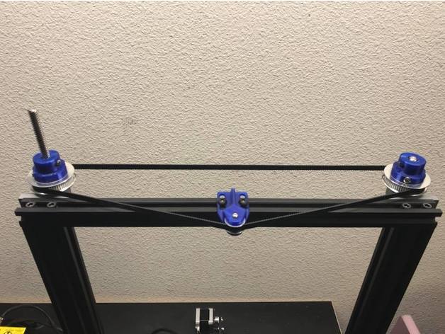
CR-10 Dual Z Pulley Setup 3D Print Model
Summary
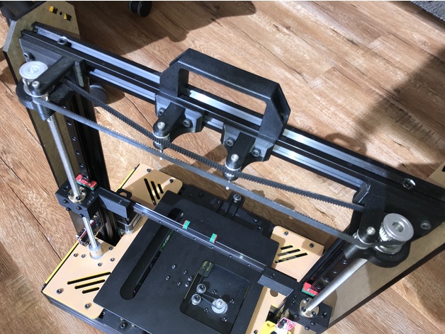
As requested here are the files for the dual Z setup I recently set up. One of my main design goals was to not use any set screws. Here are the specific parts I used.
T8 600mm 3D Printer Stainless Steel Lead Screw Coupling Shaft Mounting Bearing
Link: http://r.ebay.com/eVLz50
BIQU GT2 Synchronous Wheel 60 Teeth 8mm Bore Aluminum Timing Pulley for 3D Printer 6mm Width Belt (Pack of 2pcs)
BIQU
Link: http://a.co/eORAb49
BIQU GT2 20Teeth 3mm Bore Aluminum Timing Belt Idler Pulley for 3D Printer 6mm Width Timing Belt (Pack of 5pcs)
BIQU
Link: http://a.co/iPQ3g65
Uxcell a16031400ux0530 3D PRINTER 2GT-6 Ring Closure Timing Belt Closed 852mm Circumference, HSS
uxcell
Link: http://a.co/bhJZ4WH
Print Settings
Printer:
Hictop CR-10 Rafts:
Doesn’t Matter Supports:
Yes Resolution:
.2mm Infill:
50% -
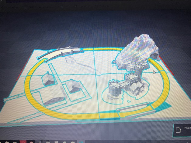
Z Gauge 220 diorama Marklin 3D Print Model
Summary
Layer: 0.1
Printer: Prusa I3
Split to 4 parts – total scaled to A3 format [ 29.7 x 42 ], -
Lower Z axis mount (Ooznest Ox Style) 3D Print Model
Summary
Solved an issue my OX Cnc was having where the bore was wearing down and allowing the bearing to slide through. added a small lip on the bottom edge to keep the bearing in place..
Print Settings
Printer:
Mp Select Mini V1 Rafts:
No Supports:
No Resolution:
0.2 Infill:
75% -
Homemade Laser Plotter Draw Mill 3D Printer Arduino Robotic Drawing DIY Z Axis Slide Linear Frame 3D Print Model
Summary
DIY Y Axis Frame here: https://www.thingiverse.com/thing:2544021
DIY Bed Base Frame here: https://www.thingiverse.com/thing:2490465
DIY Y Axis Bed Base Frame here: https://www.thingiverse.com/thing:2543717 -
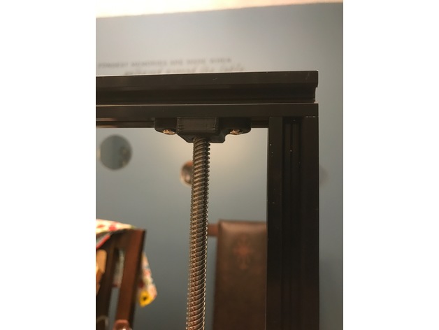
Z Top Fix 3D Print Model
Summary
There is an issue on original Z axis rod where the Z rod are neither parallel nor perpendicular ! More details here : https://github.com/prusa3d/Original-Prusa-i3/issues/34
This z axis top solve the problem plus it makes the bracket stronger and it increases the support of Z rod (should reduce Z wobble as well).
It is compatible with Prusa i3 MK2, MK2s and MK2.5.
Please note that you should have a space of 0.5mm between the top of the Z rod and the smaller circle, this is made on purpose. Do not push the rod to the “cap” of this piece but screw it and check that it is square to the frame.
Print Settings
Printer Brand:
Prusa Printer:
i3 MK2S Rafts:
No Supports:
No Resolution:
0.20 Infill:
30-40% Notes:
Use PETG or ABS filament.I am using Extrudr MF-PETG Neon Orange which is very very close to Prusa orange.
3 perimeters
4 top
4 bottom
30-40% infill
seam_position : aligned (Print settings -> Layers and perimeters -> Advanced -> Advanced)
Might be good to reduce the speed a bit because of the small surface on the end of the print. -
Prusa i4 Single Stepper Belt Driven Z Axis Modification 3D Print Model
Summary
Never one to just assemble the kit, here is one of the modifications I’m making to my Prusa i4 before I have it up and running.
Required parts:
2 x GT2 Timing Gear Pulley 30 Tooth Bore 8MM
2 x 608Z Flange Bearing
8 x M5 bolt
8 x T-Nut for 20×20 TSlot
4 x M3 bolts at least 20mm long
2 x GT2 Timing Gear Pulley 16 Without Teeth Bore 3MM
2 x GT2 Timing Gear Pulley 16 Tooth Bore 3MM
2 x Anti Backlash Spring Loaded Nut for 8mm Threaded Rod Lead Screws
1 x Bearing Block KFL08
1 x A 6R51M345060 GT2 Belt
Print Settings
Rafts:
Doesn’t Matter Supports:
Yes Resolution:
0.2mm Infill:
15% Notes:
I didn’t add supports in the horizontal holes -
Z Rod Anti Wobble v2 3D Print Model
Summary
this is just an upgrade version z rod anti wobble as requested by FxDx i hope you like it.
old version support z stop https://www.thingiverse.com/thing:2480900
Print Settings
Printer:
Anet A8 Rafts:
No Supports:
No Resolution:
0.2 -
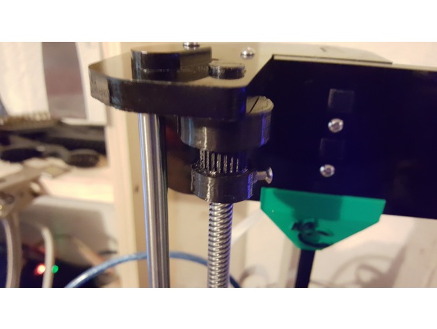
Anet A8 (Prusa) Z axis synchronising gizmo, 608 bearing 3D Print Model
Summary
Modified for the 608 bearing. Changed the 2 pulleys to one pulley, and added .1 to the inner diameter, and swapped out the toothed pulley for deeper toothed one (by Grimlock_UK).
Print Settings
Printer:
Anet A8 Rafts:
No Supports:
No Resolution:
.2 Infill:
30 Notes:
See original post by FredGenius for instructions and tool to put belt together.https://www.thingiverse.com/thing:2350350 -
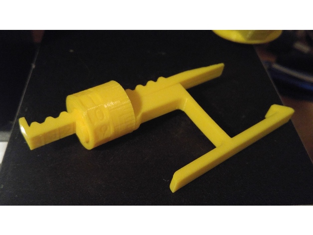
Anet A8 Z Axis Height Gauge 3D Print Model
Summary
A quick design of a thing used to help set and check the Z axis height. I rotated the object 90 degress so that the large diameter is at the bottom of the print I then multiplied it by 1 to print 2 each. -

Nissan 370z Nismo 2014 VRAY 3D Model
————————————————————————————— High detailed model created by SQUIR team.—————————————————————————————Ready to render at 3dsmax with VRAY.It was rendered at 3dsmax 2015 with vray3.20Rendering scene with all lightning, materials, background setups is included. 3dsmax 2010 format is also included, but without the rendering setups.All of our models was made on the 3dsmax, and we are able to provide uncollapsed modifier stack only for the 3dsmax, but if you’d need the lower polygon version at other programs, please contact with the support, and we will convert the reduced mesh to requested format. For this product there’s 3 different 3dsmax files included.’Set’ is uncollapsed, it’s a file where you can make changes at the model. ‘Hipoly’ is collapsed to hipoly with all the modifiers history cleaned to make it trouble free while using at other programs’Studio’ is the file with all rendering setups that we used to make the previews renderings.Because of different Disk topology at different computers it might be required to change the textures path at the destination computer.————————————————————————————— Thank you for buying SQUIR models—————————————————————————————
-

Nissan 370z Nismo 2017 VRAY 3D Model
————————————————————————————— High detailed model created by SQUIR team.—————————————————————————————Ready to render at 3dsmax with VRAY.It was rendered at 3dsmax 2015 with vray3.20Rendering scene with all lightning, materials, background setups is included. 3dsmax 2010 format is also included, but without the rendering setups.All of our models was made on the 3dsmax, and we are able to provide uncollapsed modifier stack only for the 3dsmax, but if you’d need the lower polygon version at other programs, please contact with the support, and we will convert the reduced mesh to requested format. For this product there’s 3 different 3dsmax files included.’Set’ is uncollapsed, it’s a file where you can make changes at the model. ‘Hipoly’ is collapsed to hipoly with all the modifiers history cleaned to make it trouble free while using at other programs’Studio’ is the file with all rendering setups that we used to make the previews renderings.Because of different Disk topology at different computers it might be required to change the textures path at the destination computer.————————————————————————————— Thank you for buying SQUIR models—————————————————————————————
-
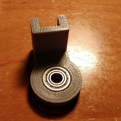
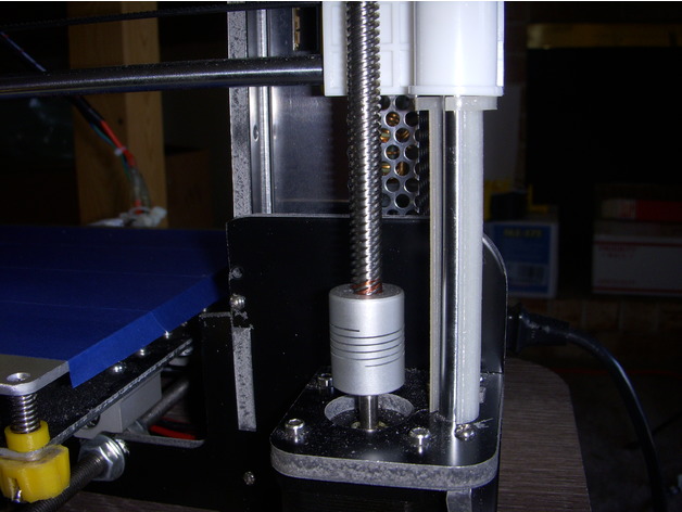
Tronxy x3 Z leadscrew stabilizer bearing support 3D Print Model
Summary
I needed a stabilizer that would house a 16mm bearing, as that is all I had. So I designed these instead of using the 22mm 608z skate bearings. The bearing is a 16x5x8. Enjoy.
Print Settings
Printer:
Tronxy X3 Rafts:
No Supports:
Doesn’t Matter Resolution:
.2 ish Infill:
your liking -
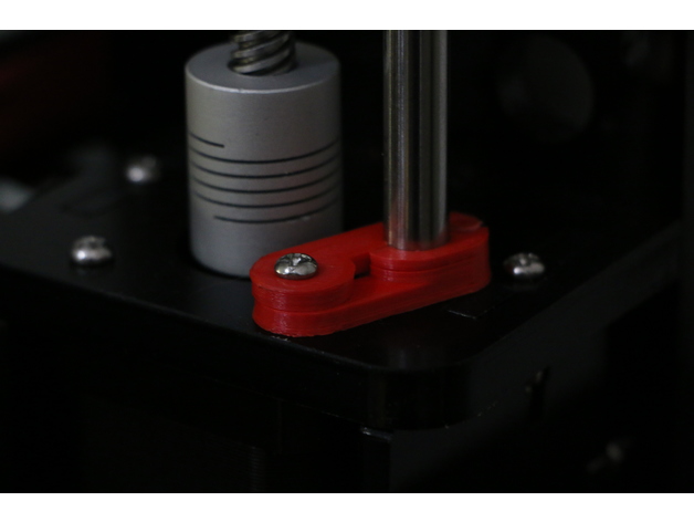
Geeetech improved Z adjust 3D Print Model
Summary
Geeetech prusa i3 axis wobble fix
by shawdreamer, published Sep 17, 2016
Added adjust screw stabilizer, reversed Z Nut to make better. Included Prt. to modifly as needed -
ZTE Nubia Z9 Black 3D Model
The 3D model was created on real base. It’s created accurately, in real units of measurement, qualitatively and maximally close to the original.Model formats:- *.max (3ds Max 2008 scanline)- *.max (3ds Max 2008 vray)- *.fbx (Multi Format)- *.obj (Multi Format)- *.3ds (Multi Format)- *.mb (Maya 8.5)- *.lwo (Lightwave 6)- *.c4d (Cinema 4D 11)* renders Are made in 3ds Max 2008 using vray 1.5 (studio environment is not included in the set)If you need any other formats we are more than happy to make them for you.The model is provided combined, all main parts are presented as separate parts therefore materials of objects are easy to be modified or removed and standard parts are easy to be replaced. If you experience difficulties with separating standard parts we are more than happy to give you qualified assistance.We greatly appreciate you choosing our 3D models and hope they will be of use.We look forward to continuously dealing with you.Sincerely Yours,Hum3D Team
-
Casio Exilim EX- Z1050 Black 3D Model
The 3D model was created on real base. It’s created accurately, in real units of measurement, qualitatively and maximally close to the original.Model formats:- *.max (3ds Max 2008 scanline)- *.max (3ds Max 2008 vray)- *.fbx (Multi Format)- *.obj (Multi Format)- *.3ds (Multi Format)- *.mb (Maya 8.5)- *.lwo (Lightwave 6)- *.c4d (Cinema 4D 11)* renders Are made in 3ds Max 2008 using vray 1.5 (studio environment is not included in the set)If you need any other formats we are more than happy to make them for you.The model is provided combined, all main parts are presented as separate parts therefore materials of objects are easy to be modified or removed and standard parts are easy to be replaced. If you experience difficulties with separating standard parts we are more than happy to give you qualified assistance.We greatly appreciate you choosing our 3D models and hope they will be of use.We look forward to continuously dealing with you.Sincerely Yours,Hum3D Team
-
Maker Select v2 Z axis Bearing Mounts 3D Print Model
Summary
previously I created a set of X-ends for the Monoprice Maker Select v2 to replace the stock metal ones because I wanted a way to use standard LM8UU bearings for the z-axis. Those have been installed on my printer for the last couple of months, but I figured I’d try making a set of bearing holders in case any of you want to use different bearings, but are happy with the metal x-ends that your printer came with.
These seem to work pretty well. Just screw them in from the bottom, slide the bearing into place, and you should be good to go.
I printed these in ABS with 4 perimeters and 40% infill, but the walls are pretty thin so you could probably do them 100% infill and it wouldn’t make much difference in print time. -
delta legs x y z 3D Print Model
Summary
It’s to remember what tower is what X Y Z
and Feet to X Y Z legs -
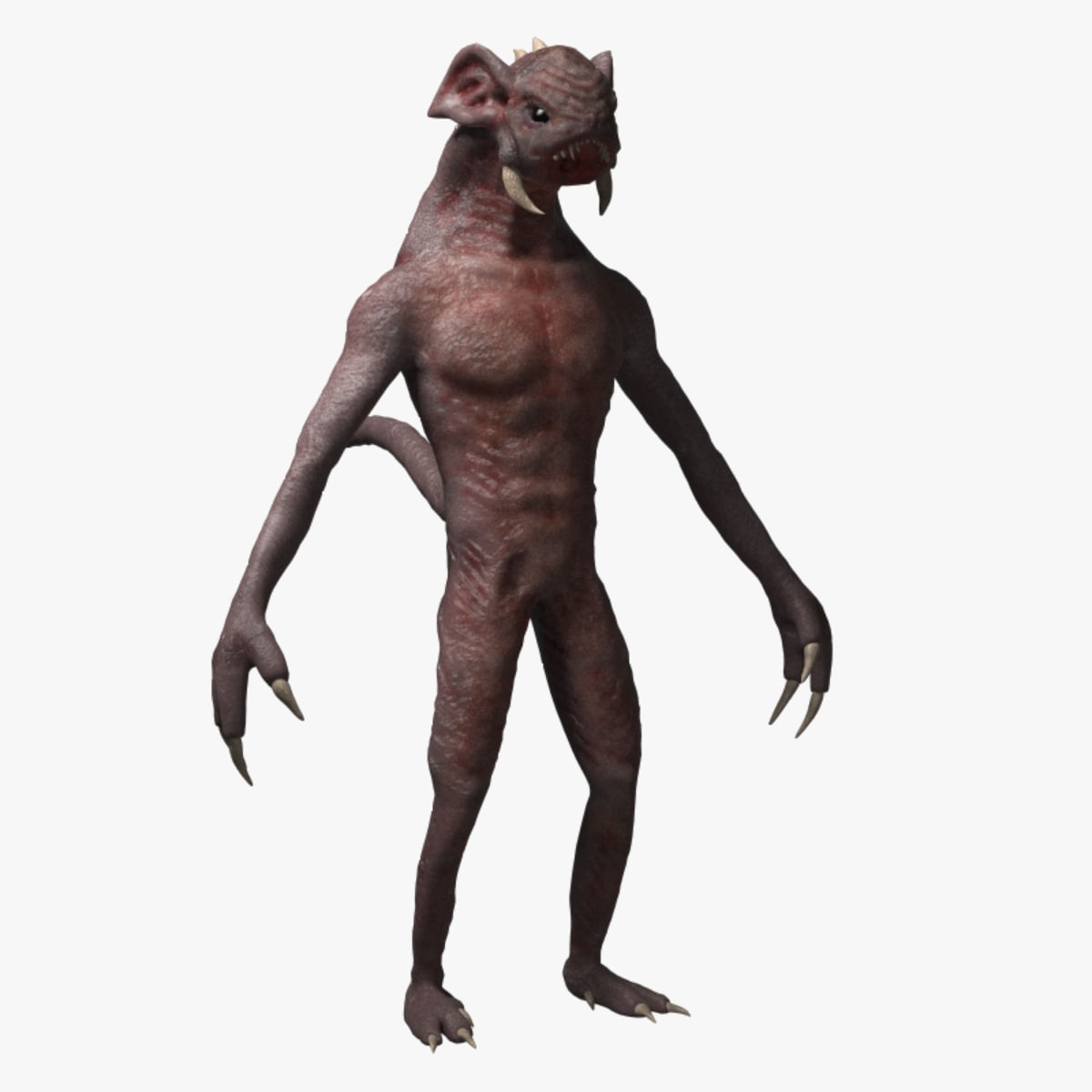
Creature Z (Rigged) model 3D Model
This Rigged Creature Z model is a high quality model that will enhance detail and realism to any of your rendering projects. The model has a fully textured, detailed design that allows for close-up renders, and was originally modeled in Zbrush 4R7 and rendered in 3ds Max 2016 with V-Ray 3.4 *********************************Features:-Low-Poly polygonal model, correctly scaled for an accurate representation of the original object.-Models resolutions are optimized for polygon efficiency. (In 3ds Max, theTurbosmooth function can be used to increase mesh resolution if necessary.)-Model is fully textured with all materials applied.-All textures and materials are included and mapped in every format.-3ds Max model objects are logically named for ease of scene management.-No part-name confusion when importing several models into a scene.-No cleaning up necessaryjust drop your models into the scene and start rendering.-The model is rigged and skinned properly and has all controls. Also has extra controls for fingers and foot roll.-Game Ready model.*********************************File Formats:- 3ds Max 2016 V-Ray- OBJ (Multi Format)Every model has been checked with the appropriate software.Zbrush is original file that has all subdivisions and detail in the mesh.*********************************Textures Formats:2 number of images .tiff 8192 x 81922 number of images .psd 8192 x 8192*********************************Hope you like it!Also check out my other models, just click on my user name to see complete gallery
-
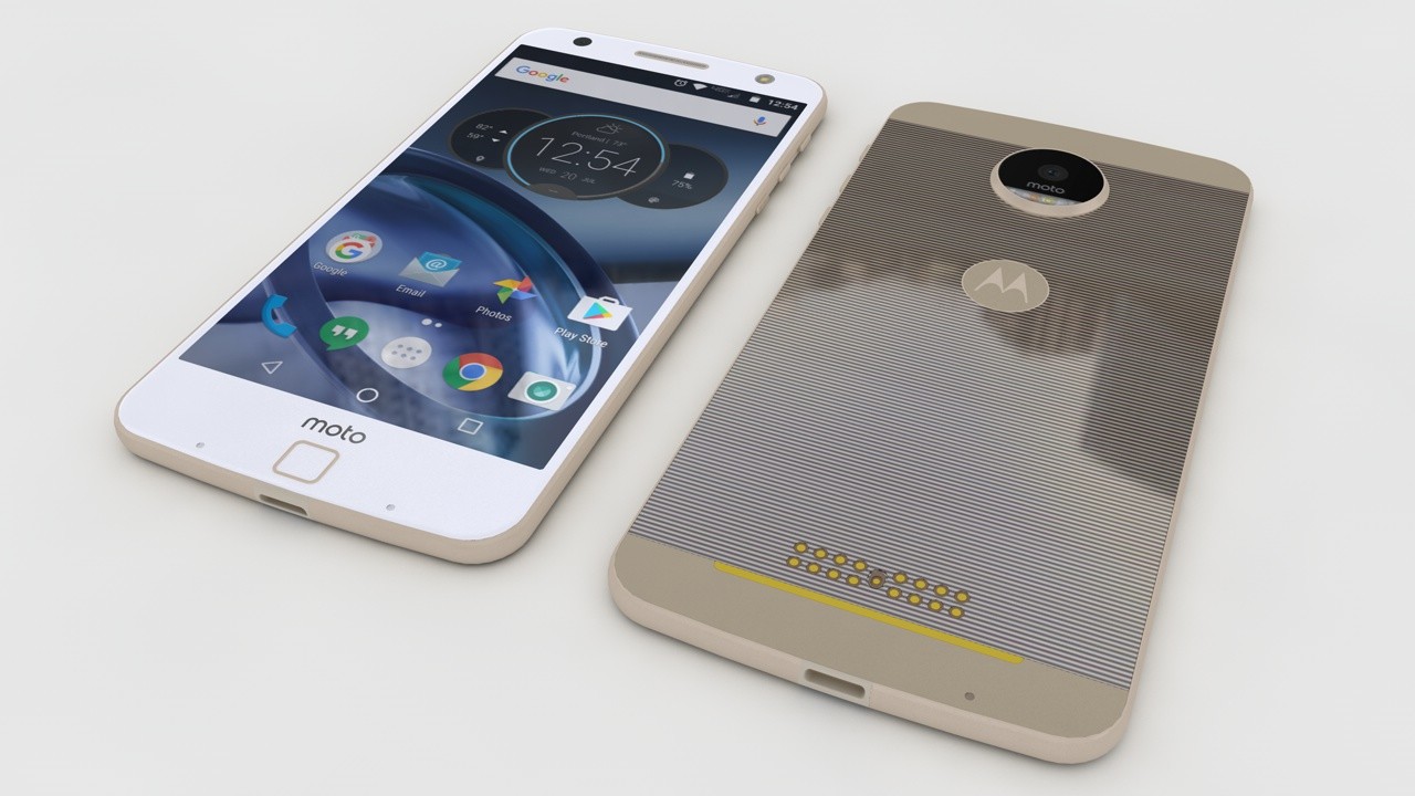
Motorola Moto Z Lenovo 3D Model
Modeled with Solidworks , Rendered with Cinema 4D.Very High detailed 3D model.NOTE: This project is ready for render and all textures that you are need are in the tex folder, C4D version only. All other formats will need textures re-applied.
-
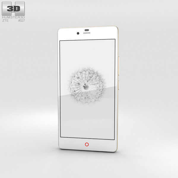
ZTE Nubia Z9 Mini White 3D Model
The 3D model was created on real base. It’s created accurately, in real units of measurement, qualitatively and maximally close to the original.Model formats:- *.max (3ds Max 2008 scanline)- *.max (3ds Max 2008 vray)- *.fbx (Multi Format)- *.obj (Multi Format)- *.3ds (Multi Format)- *.mb (Maya 8.5)- *.lwo (Lightwave 6)- *.c4d (Cinema 4D 11)* renders Are made in 3ds Max 2008 using vray 1.5 (studio environment is not included in the set)If you need any other formats we are more than happy to make them for you.The model is provided combined, all main parts are presented as separate parts therefore materials of objects are easy to be modified or removed and standard parts are easy to be replaced. If you experience difficulties with separating standard parts we are more than happy to give you qualified assistance.We greatly appreciate you choosing our 3D models and hope they will be of use.We look forward to continuously dealing with you.Sincerely Yours,Hum3D Team
-
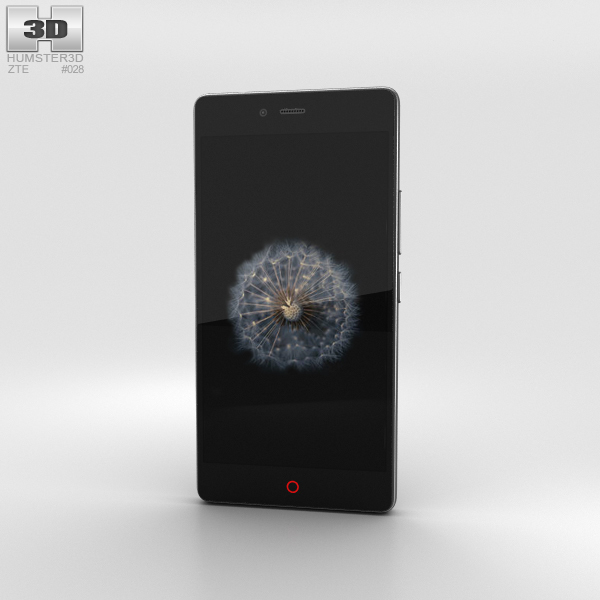
ZTE Nubia Z9 Mini Black 3D Model
The 3D model was created on real base. It’s created accurately, in real units of measurement, qualitatively and maximally close to the original.Model formats:- *.max (3ds Max 2008 scanline)- *.max (3ds Max 2008 vray)- *.fbx (Multi Format)- *.obj (Multi Format)- *.3ds (Multi Format)- *.mb (Maya 8.5)- *.lwo (Lightwave 6)- *.c4d (Cinema 4D 11)* renders Are made in 3ds Max 2008 using vray 1.5 (studio environment is not included in the set)If you need any other formats we are more than happy to make them for you.The model is provided combined, all main parts are presented as separate parts therefore materials of objects are easy to be modified or removed and standard parts are easy to be replaced. If you experience difficulties with separating standard parts we are more than happy to give you qualified assistance.We greatly appreciate you choosing our 3D models and hope they will be of use.We look forward to continuously dealing with you.Sincerely Yours,Hum3D Team
-
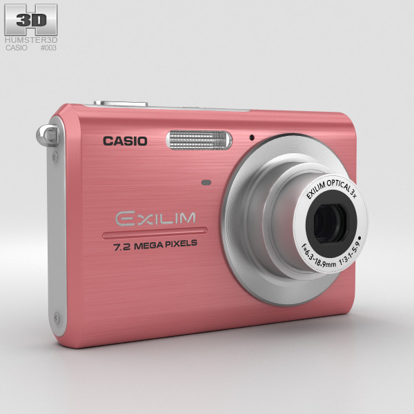
Casio Exilim EX-Z75 Pink
The 3D model was created on real base. It’s created accurately, in real units of measurement, qualitatively and maximally close to the original.Model formats:- *.max (3ds Max 2008 scanline)- *.max (3ds Max 2008 vray)- *.fbx (Multi Format)- *.obj (Multi Format)- *.3ds (Multi Format)- *.mb (Maya 8.5)- *.lwo (Lightwave 6)- *.c4d (Cinema 4D 11)* renders Are made in 3ds Max 2008 using vray 1.5 (studio environment is not included in the set)If you need any other formats we are more than happy to make them for you.The model is provided combined, all main parts are presented as separate parts therefore materials of objects are easy to be modified or removed and standard parts are easy to be replaced. If you experience difficulties with separating standard parts we are more than happy to give you qualified assistance.We greatly appreciate you choosing our 3D models and hope they will be of use.We look forward to continuously dealing with you.Sincerely Yours,Hum3D Team
-
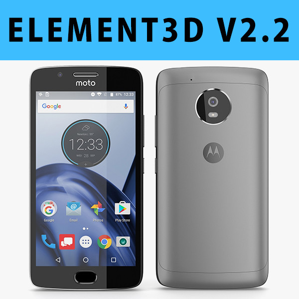
E3D – Motorola G5 Space Gray
This pack:Element 3D V2.2 ( All colors )models preset easy to use- 1 file OBJ High poly- 1 file OBJ standard- 1 file C4D R12 standard render- 1 file 3ds max 2012 standard material- E3D file full materials set up like previewsHow to use it?1. Open After Effects CC 2014 ( or higher) and create new composition ( You need Element3D V2.2 to use )2. Create new Solid layer and add Element effect. ( Effect/Video Copilot/ Element )3. Click Scene Setup4. Click on IMPORT inside Element3D scene setup5. Choose my .e3d preset for the model and press Open.If you dont see the model do not forget to right click on the model name and press Replace model then select the .obj model file in the respective models folder.