Summary
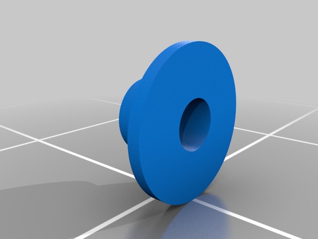
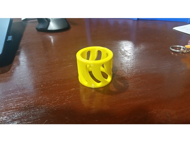
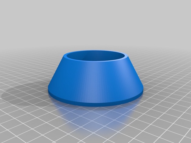
Camera spacer for Puda 220 frame for camera mouting.
As holes for camera screws is larger than necessary, made this simple spacer, to center screw. Tested with Runcam Owl Plus, but probably fits other as well.
Tag: Spacer
-
Camera spacer for Puda 220 3D Print Model
-
3.50mm Omnibus F3 Raised Spacer 3D Print Model
Summary
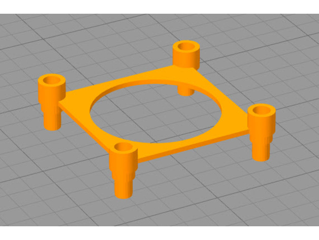
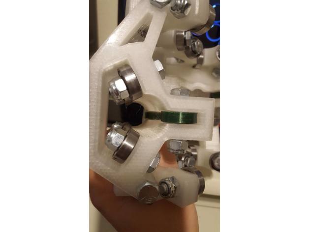
This is a remix of JerryBoi831’s design.
Simple raised PDB mount. Utilized to mount a PDB and FC to my Bixler 3
Print Settings
Printer Brand:
Prusa
Printer:
i3 MK3
Rafts:
Doesn’t Matter
Supports:
Yes -
Cooling Fan Spacer for A6 with lights 3D Print Model
Summary
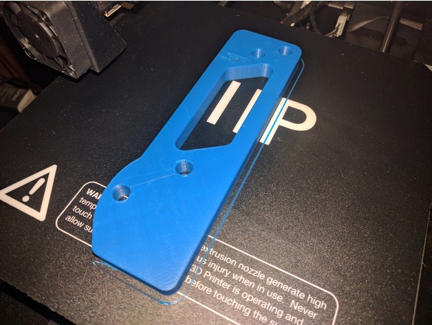
The original fan spacer works great. I wanted some light down by the print nozzle, so I could watch the print without using a flashlight. I modified the spacer to add an area for LEDs. I stuck a small strip of LEDs on and wired them into the extruder fan power.
I’m quite happy with the result. Soldering into the existing fan wiring (while it was still on the printer) was a bit of a PITA. I didn’t want to completely undo the loom and remove the fan from the printer, so that’s how it had to be. Still, well worth it.
Print Settings
Printer:
Anet A6
Rafts:
No
Supports:
Yes
Resolution:
.2 mm
Infill:
100%
Notes:
I printed at 100% infill. Once you print the walls, there’s not much left on the inside I figured why not. Print with supports and a brim. Print in the orientation shown on the model here. Its minimal support and it comes off very easily.
Post-Printing
LEDs
I bought a meter long strip of 12v LEDs for about $1. I cut off a 45mm section and attached it to the bottom of this part. I soldered on servo wire, and then soldered those wires to the power leads going to the extruder fan. For extra security, I put some Kapton tape around the LED strip as well (also to cover up the exposed solder points). -
MPSM Fully Adjustable Z Spacer (MP Select Mini) 3D Print Model
Summary
Fully Adjustable Z Spacer
MP Select Mini
By Wiley Kyoto
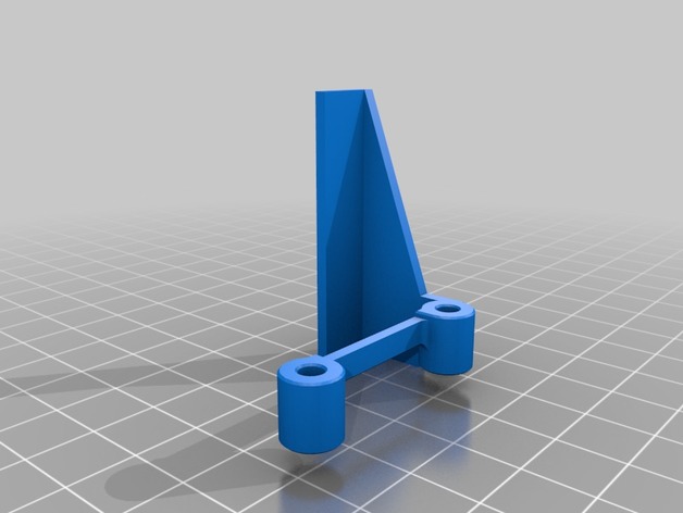
This Z spacer is designed to give you continuous adjustment from 1mm to 5mm. If you want to switch between the stock bed and glass bed, you don’t have to adjust your print bed and then re-level it. If the beds already level, just adjust the spacer for the change in height to account for the glass thickness. Also If you change nozzles, the new one might be slightly longer or shorter, so just adjust the Z offset accordingly. I gave the Bracket a slight bend so it keeps constant pressure to hold it firmly in place.
My Print Setup:
PLA
210/60C
No Supports
0.175mm Layer Height
1.4mm Wall Thickness
1.05mm Top and Bottom Thickness
Orientation – Lay the AdjArm and Bracket flat on their sides. Put the AdjDial on one of the flat ends (I had numbers near the top).
Assembly:
Put the AdjDial on the Bracket, in the groove next to the indicator mark, with the numbers closest to the outside edge.
Insert the sloped edge of the AdjArm through the AdjDial, with the threads of the AdjArm facing away from the Bracket.
Keep pressure pushing the AdjArm into the AdjDial as you start to turn the AdjDial clockwise. Keeping in mind that the thread is reversed thread, such that turning the AdjDial clockwise will wind the AdjArm farther in.
Set the AdjDial to roughly the right spot (See Reading the Dial).
Make sure the head position of the printer is a good couple centimetres in the +Z direction, to prevent damage to the Z limit switch.
Insert the assembled spacer through the vertical slot in the back of the printer tower, snapping it into place on the Z Bearing Block(Black Plastic Block with metal rods running vertically through it), which you can see through the vertical slot. You should hear and feel a solid click as it snaps securely into place, pushing forward firmly on the top lever of the spacer should help it snap into place.
Make final adjustments the the AdjDial but homing the printer and checking the fit with a piece of paper under the nozzle.
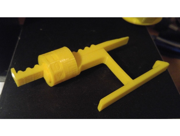
Reading the Dial:
Note – the readings won’t have absolute accuracy as it depends on the exact placement of the Z Limit switch, but the relative accuracy should be great.
The AdjArm has 4 notches, with numbers 1 to 4 next to them. These represent whole mm steps.
The AdjDial has 40 notches, every 4 notches are numbered .0 through .9. These represent decimal mm steps. Each notch is a 0.025mm step.
The Bracket has one indicator notch which lines up with the notches on the AdjDial to indicate where to read the setting.
When the outside edge of the Bracket is lined up with the first notch(next to the 1) on the AdjArm and the .0 setting on the AdjDial is centred on the indicator notch, the spacer is set to 1.0mm.
When the AdjArm is all the way into the AdjDial, and the AdjDial is set to .0, the spacer is set to 5.0mm.
The spacer can be set less than 1mm but at some point (around 0.7mm on my printer) the limit switch will slip off the end of the spacer and effectively act as 0mm offset. -
Cr-10 Spool Adapter and Spacer 3D Print Model
Summary
I didn’t like the way the spools rode on the shaft for the Cr-10, so I designed up this spool adapter. If you print one for each side of the spool, they fit over the shaft and inside the spool ID for a much better fit. This also ensures the nut holds the material on, without over tightening. Designed for the Inland 1.75mm 1Kg spools, but works for others as well.
I also recently picked up smaller test spools for glow in the dark and color changing material, and found they were thinner causing the adapters to walk out during printing, so I designed up a quick spacer to solve that problem as well.
Thanks,
Johnny Mac
Print Settings
Printer:
CR-10 Rafts:
Yes Supports:
No Resolution:
.1 layer thickness Infill:
25 Notes:
I used the raft to keep the spool flat against the build plate, but it would likely print without. PLA works fine as these take no load. -
MPCNC spacer for 608zz to remove any play in rails 3D Print Model
Summary
This is a simple spacer you can put on your 608zz bearings to make the ride more smooth without any play. PLA worked great for me and make sure your increase or lower your layer width so you have a good bond. .44 worked for me on a .4 nozzle -
10mm Punch and Die set spacer 3D Print Model
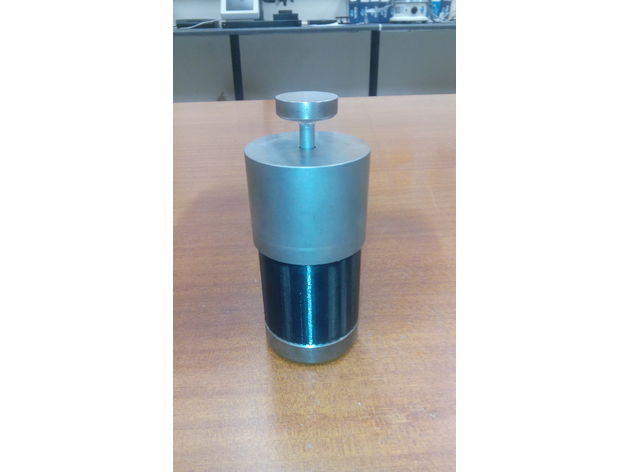
Summary
This is a spacer for a 10mm die set. Used to create a floating die for compaction in both downward and upward directions. -
Vesa Spacer 100mmX100mm 3D Print Model
Summary
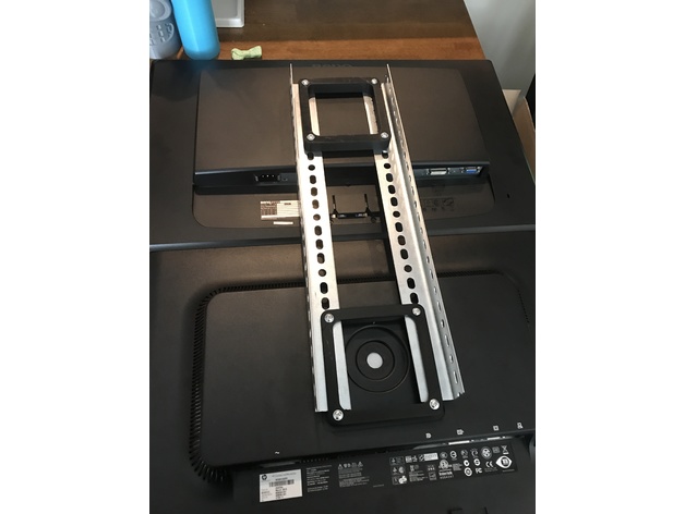
Basically I needed a spacer that was more than just tubes. So I drew this up using free cad. Its easy to make it different thicknesses just turn off uniform scaling and move the z up and down as you need.
feel free to remix. Its a bit of a long print and uses some plastic. I needed it to be structurally substantial not just a spacer.
Having all 4 hole connected made installing it a lot easier than if you have for separate tubes.
Print Settings
Printer Brand:
Wanhao Printer:
Wanhao Duplicator i3 V2 Rafts:
No Supports:
No Resolution:
what every you feel like. I did 0.2 Infill:
50% more than that takes a long time. Notes:
The resolution walls and infill are all up to you it really doesn’t matter for successful print. What matter is where and how you are going to use it.
I did 4 walls, 50% infill, @ 0.2. My printer struggles with 0.3
How I Designed This
Free cad
this one is simple. The spec is 100 x 100 mm on center.
1 Make a square that is 120 x 120 mm and center it on the X Y plain
2 Place holes 100 x 100 MM centered on x Y plain.
3 Pocket square I think 80 X 80 or maybe 90 x 90
4 Fillet inside corners and outside corners 10 mm fillets. -
spacer for spool holder 3D Print Model
Summary
can hold spools from Ø + – 60 to 80
Print Settings
Supports:
No Resolution:
0.2 /0.1 Infill:
20 – 25% -
Focus ST Pedal Spacer
Summary
The Focus ST acceleration pedal default position is highly recessed. This spacer moves the pedal forward to put it more in line with the other pedals. The 9.6 mm thickness should install with the default hardware. I designed it based on a 2017 Focus ST, but it should fit any Third Generation Focus (2012 to now).
You MUST use ABS or similar that has a higher glass transition temperature. Using a low transition temperature material (like PLA) can fail when typical temperatures are reached in hot cars.
Print Settings
Printer Brand:
Wanhao Printer:
Wanhao Duplicator i3 V2 Rafts:
No Supports:
No Resolution:
0.2mm Infill:
60 Notes:
I used 40% infill which seems to work, but I think 60%+ would be better suited for this.
ABS or similar should be used.