The 3D model was created on real base. It’s created accurately, in real units of measurement, qualitatively and maximally close to the original.Model formats:- *.max (3ds Max 2008 scanline)- *.max (3ds Max 2008 vray)- *.fbx (Multi Format)- *.obj (Multi Format)- *.3ds (Multi Format)- *.mb (Maya 8.5)- *.lwo (Lightwave 6)- *.c4d (Cinema 4D 11)* renders Are made in 3ds Max 2008 using vray 1.5 (studio environment is not included in the set)If you need any other formats we are more than happy to make them for you.The model is provided combined, all main parts are presented as separate parts therefore materials of objects are easy to be modified or removed and standard parts are easy to be replaced. If you experience difficulties with separating standard parts we are more than happy to give you qualified assistance.We greatly appreciate you choosing our 3D models and hope they will be of use.We look forward to continuously dealing with you.Sincerely Yours,Hum3D Team
Tag: pulley
-
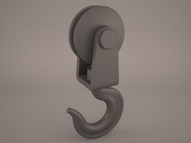
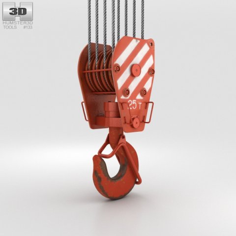
Hook pully 3D Model
pulley hook crane shipping cargo transport pull claw grip pully construction tow utility industrial heavy duty spring tool elevator part metal detail
-
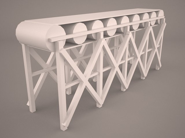
Belt Conveyor 3D Model
Belt Conveyor carrying system pulley factory warehouse carrier mine quarry assembly line vray
-
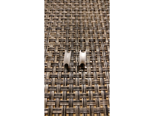
Blinds lift pulley 3D Print Model
Summary
I was shortening some window blinds, when one of the little pulley wheels got lost. I measured one of the other wheels and modeled it in Fusion 360.
Print Settings
Printer:
Monoprice Select Mini
Rafts:
No
Supports:
No
Resolution:
0.2
Infill:
100 -
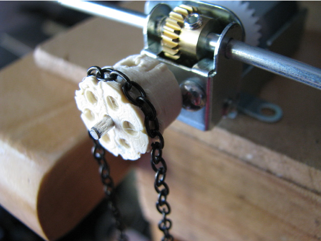
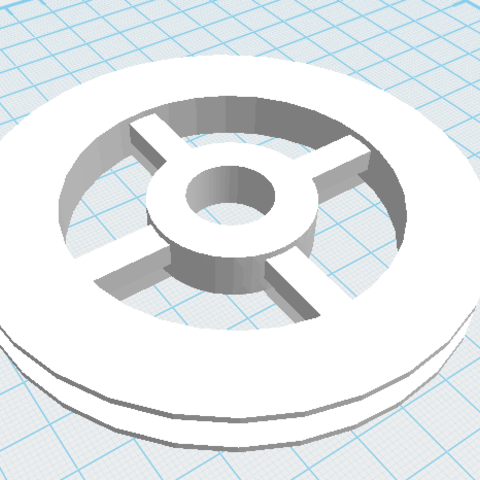
Parametric Chain Link Drive Pulley 3D Print Model
Summary
I had a desire to make some small chain drives for some of my models, but wanted to use some classic chain link style chair rather than proper chain drive chain. I had a look on thingiverse and discovered that nobody else had made a model for this. So, after scratching around with a pencil to work out what parameters I needed, I jumped on OpenSCAD and came up with two parametric models. This one has a neck, holes and nut slots for screwing it onto a shaft while the other is just a disk with the chain recesses which can be more easily adapted to other pulley body designs.
The chain size and number of link pairs determines the size of the pulley. So the important variables to fiddle with are;
Llength: This is the outside length dimension of a single linkLwidth: This is the outside width dimension of a single linkLthickness: This is the diameter of the link “wire”
N: The number of chain link pairs around the pulley. Please note this is pairs of links not the number of single links.
The pulley neck size is controlled by the following parameters;
Pwidth: Width of the pulley main drum which the chain recesses are cut into.PstemD: This is the diameter of the pulley attachment neck. There is nothing to stop you putting dimensions in here that can’t accommodate the retaining screw or the shaft. We leave that to you, the user, to figure something sensible.PneckL: This is the desired neck length
AxleD: This is the axle diameterScrewD: This is the retaining screw diameter
There are a bunch of other parameters that you may wish to tweak too;
Ptol: Is the printing tolerance. It is used to provide a bit of space around the chain profile so that chain will fit into the recess despite a bit of spread from the extruded plastic.PtolThk: This is a printing allowance for the “radially” orientated link thickness. This allows a bit of extra on either side of the link slot so any sagging of the printed filament can be easily removed or at least won’t interfere with the link sliding into the slot.Wclr: On either side the the tangential link is a cutout slot. This parameter just controls the size of this slot.
CutD:There are some very stylish decorative holes in the end of the pulley. This parameter controls the diameter of these.CutN: This controls the number of these extremely stylish holes.
Hopefully this is all clear enough.
I feel the model will work well for larger chains where the printing tolerances are less of a factor in the final printed shape.
I trust this will be useful to you. -
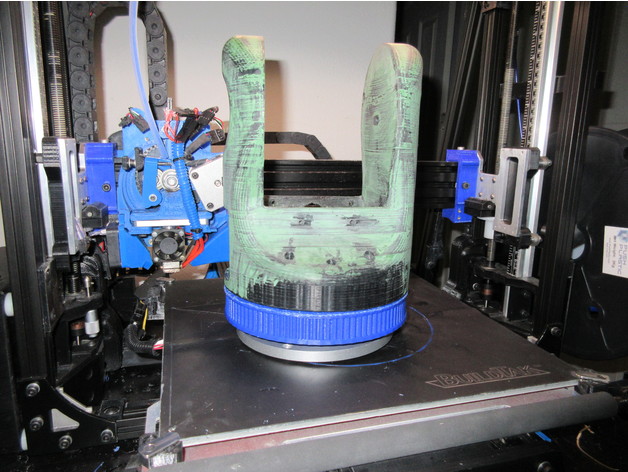
Turret Ring Slew Bearing base and main pulley for Moveo Robot Arm 3D Print Model
Summary
This is another modification based off of Labala’s excellent Moveo upgrade parts. This time I’ve bored out the main pulley for arm rotation and made a matching base for it. This uses an inexpensive 5.5″ (140mm) turntable bearing (I used this one specifically https://www.ebay.com/itm/1pc-new-5-5-140mm-Home-Hardware-Aluminum-Round-Lazy-Susan-Bearing-Turntable/122799616711?ssPageName=STRK%3AMEBIDX%3AIT&_trksid=p2060353.m2749.l2649) as well as 8 M4 trapazoid head bolts and nuts. 35mm – ish should work fine. You may need to go with phillips head ones in this instance to get proper countersink clearance.
Assembly instructions:
you will need the other half of the base, the motor mount, cover and belt tensioner from Labala’s project.
install the ring on the printed base, with the ring clearance extension down, make sure the bolts are tight. Consider using lockwashers here.
install the nuts in the pulley ring, and bolt it to the stock arm base using the stock bolts.
bolt the turntable slew bearing to the bottom of the pulley
Assemble the remaining base components.
Thats it, you now should have a robot arm you can bolt to a baseplate or something.
Future expansion plans will include some sort of mount for a 2 stage slip ring assembly (large outer 12 ring, smaller inner 24 ring maybe?
I’m printing the larger piece now, will post pictures when it’s done.
Print Settings
Printer Brand:
LulzBot Printer:
TAZ 5 Rafts:
No Supports:
Yes Resolution:
0.5mm nozzle, ABS (PLA might work better here) Infill:
15% infil, 7 shells. Notes:
This is going to require support for the mounting tabs and the slew ring recess. -
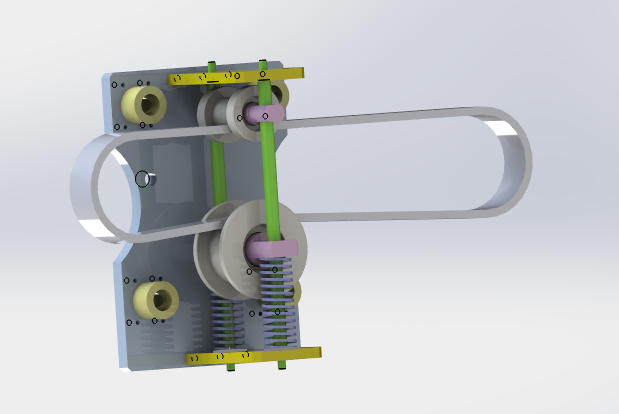
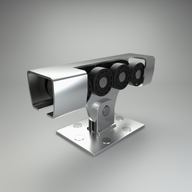
Belt tightening pulley 3D Model
Belt tightening pulley.It is a kind of commonly used tensioning structure, which is used to tighten the passive wheel through the spring, and the belt is tightened by the combination of the active wheel and the passive wheelIf you like,you can paypal for you to get this models or if you have any questions also you can email to me.
-
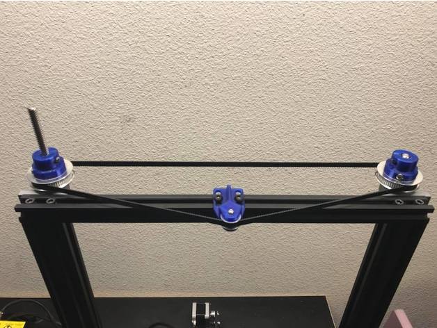
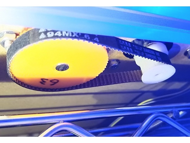
CR-10 Dual Z Pulley Setup 3D Print Model
Summary
As requested here are the files for the dual Z setup I recently set up. One of my main design goals was to not use any set screws. Here are the specific parts I used.
T8 600mm 3D Printer Stainless Steel Lead Screw Coupling Shaft Mounting Bearing
Link: http://r.ebay.com/eVLz50
BIQU GT2 Synchronous Wheel 60 Teeth 8mm Bore Aluminum Timing Pulley for 3D Printer 6mm Width Belt (Pack of 2pcs)
BIQU
Link: http://a.co/eORAb49
BIQU GT2 20Teeth 3mm Bore Aluminum Timing Belt Idler Pulley for 3D Printer 6mm Width Timing Belt (Pack of 5pcs)
BIQU
Link: http://a.co/iPQ3g65
Uxcell a16031400ux0530 3D PRINTER 2GT-6 Ring Closure Timing Belt Closed 852mm Circumference, HSS
uxcell
Link: http://a.co/bhJZ4WH
Print Settings
Printer:
Hictop CR-10 Rafts:
Doesn’t Matter Supports:
Yes Resolution:
.2mm Infill:
50% -
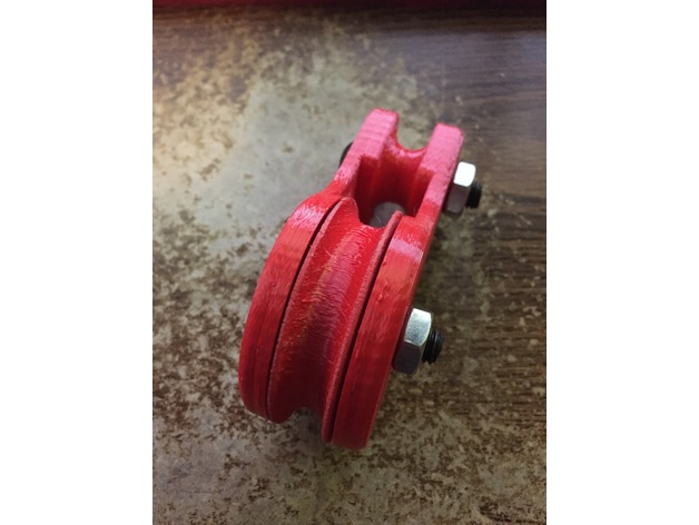
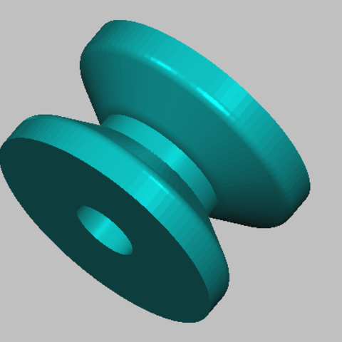
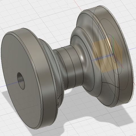
50mm Pulley (2x 608 bearing) 3D Print Model
Summary
This is a basic pulley. It has a 50mm main wheel and will handle up to a 10mm or 3/8″ line. You need two 608 skate bearings, and two 8mm x 35-40mm bolts and nuts. You can either tie a line to the top or use a carabiner as a clip. There are two wheel designs one fancy and one easier to print. I find that the wheels print well in the standing position with support. If you have problems printing that way the simpler design can be printed on its side. I may include a no bearing wheel very soon. The sides should be printed flat with 30% or more infill. I used 2mm walls, top and bottom with 30% infill. That basically makes the sides 100% with a little infill around the top block. There will be more variants, so stay tuned.
Enjoy.
If you like my designs why not tip me a dollar or two. Your support will allow me to spend more time on these designs and their variations. Thanks! -
Drive Pulley 3D Print Model
Drive pulley 100 * 100 mm.
Created from a few geometric shapes.
Can be used as a component of a construction project.
I can create the shaft that goes with it and a sprocket. -
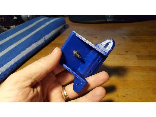
idler pulley mount for M5 bolt hole, mounts on 2020 or larger v-slot 3D Print Model
Summary
This is a simple mount for attaching to a 2020 or 2040 v-slot rail, to hold a single 5mm bore idler pulley. I needed this for my installation of a 3-leadscrew Z axis system on my D-bot.
It’s useful to help take up the slack if a belt is a little longer than needed, or to change the direction of the belt, or whatever.
A much smaller and more compact mount could be designed to hold a single 5mm bore pulley, but I just started with the Z axis bearing mount assembly that I’d remixed as part of my bearing assembly for 3 leadscrew setups.
The following thing has a photo that includes this bearing mount as part of my installed 3-leadscrew Z axis.https://www.thingiverse.com/thing:2401504
The Z axis bearing mount in that thing is a remix of the original Z axis stepper motor mount. I typically include sources in my things, but in this case I don’t have any sources. I edited the original D-bot stepper mount in Tinkercad to produce the version I used in my 3-screw bearing assemblies. For this 5mm bore pulley mount I simply filled in the hole that held the flanged bearing, filled in the screw holes, and then added a single 5mm diameter hole in the center of the mount surface.
In my case, a single M5 washer and a 7mm high aluminum spacer raised the pulley up to the same height as my other geared pulleys used in the 3-leadscrew Z axis system. Whatever spacing you need you can either fulfill by finding an appropriate spacer, stack of washers, printed spacer, or whatever.
I printed this in PETG at 260/70 C with a .4mm nozzle onto PEI. I used 98% infill to make it nice and solid. You can print this with whatever settings work with whatever filament you choose on your printer, but I’d recommend it be printed solid, since this pulley may be under considerable sideways strain if it’s being used to take up slack in a fairly tight belt. -
Rea anchor and spinnaker for Sun Odyssey 32i 3D Print Model
Boat front pulley for anchor and spinnaker.
-
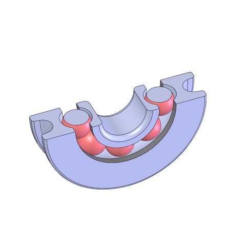
Roller bearings 3D Model
Modeled in blender of 2.78.
All the names of the meshes and materials have logical names.
The number of polygons/vertices without the use of modifiers: 34.478/35.340
All pivot points aligned.
Preview made using render Cycles.
Scene file (.blend) ready to render.
Materials made in Cycles.