Summary
Turn your Kossel from a wobbly tower that rings like a bell into a rigid, no-nonsense, crisp-printing etc. etc. etc. thing of awesomeness with these snazzy-looking anchors for steel wire frame braces and increase either your quality or speed/acceleration by a lot (or meet in the middle someplace), hurray!
It’s basically the same benefit you’d get from screwing big, thick panels of something stiff to all three sides of your printer. Or close, anyway, and waaaaaay less involved.
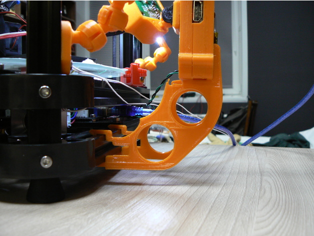
IMPORTANT DISCLAIMERS: this mod is fairly quick to print, remarkably easy to mount, has a dead cheap BOM, and offers huge and instant benefits, but it comes with the tradeoffs of a moderately reduced build envelope (basically, it’s going to cut off three outside chunks of the build platform somewhere near the inward extent of the horizontal frame members, but exactly how much depends on how far out the build plate extends over the frame horizontals, as well as your arm spacing — on my machine it’s about a 25 mm cut at the deepest) and the need to really verify your bowden/wiring clearances and look for new potential sources of wear — plus you could theoretically destroy your frame corners if you don’t take your time tensioning the setup evenly, although this mod is specifically designed to make it very difficult to apply uneven tension that would wrack your frame to death. Also, I would not recommend doing this mod without also having some compatible corner braces, like mine (https://www.thingiverse.com/thing:2474583), that will transfer twisting moments on the uprights into the horizontals, because otherwise I think this mod could eventually cam the uprights enough to split your corners.
But hey, you’re a big girl/boy and you want WARP SPEED, right? Read on to the design section and I’ll share a semi-secret that’s holding you back if you’ve never monkeyed with the stock Anycubic firmware settings, too!
Anywise. Also see the design section for all my reasoning that led to this design.
You’ll need 3 each of the adjustable and fixed anchors, 3 of the screw adjust mounts, 6 clamp washers, and 1 double eye join, plus:
1/16″ steel cable (about 4.5 meters for an AnyCubic Kossel XL, or estimate by taking your frame’s top to bottom diagonal measurement times 6 + 10%).
3x M5x20 bolts (socket head)
6x M5x12 bolts (socket head)
9x M5 nuts
15x M4x12 bolts (socket head)
15x M4 nuts
4x wire clips (preferably the screw-on kind, not the permanent ones) to fit the wire
Drinking straws in your favorite color
Kapton tape or similar
Special tools:
Wire clippers
A ball-end hex key to fit your M5 bolts will make life much easier.
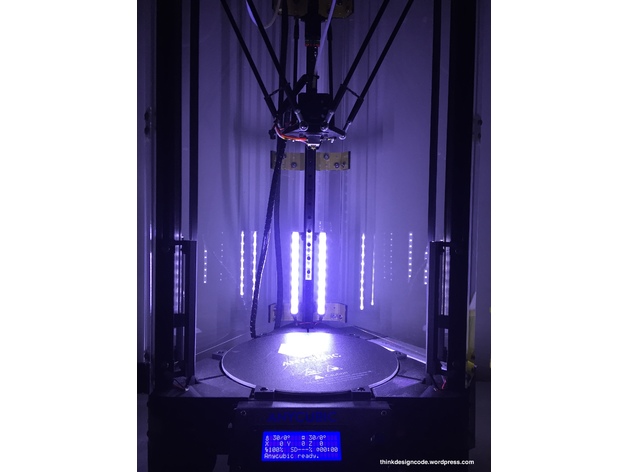
After I put this on my printer I couldn’t resist dialing up the speed and acceleration to stupid speeds and trying to print a Benchy, and I was pretty shocked when something came out in half an hour that actually LOOKED like a benchy. Is it great? Heck no! My long ol’ bowden and direct drive extruder can’t even approach keeping up with these kinds of speeds. On the other hand, the visible ringing artifacts wouldn’t have been out of place on this machine at half the speed, if that, before I put this mod on it. So at the end of the day it is a vast improvement, but like with most such mods you push out one limitation and put the pedal down only to find the next limitation waiting 🙂 In the case of my AnyCubic Kossel, it’s definitely the extruder followed by the risk of the steppers skipping when doing psycho travel moves near the outside of the build envelope.
Print Settings
Printer:
Anycubic Linear Kossel XL
Rafts:
No
Supports:
Yes
Resolution:
.2 for the anchor pieces, .1 for the washers and eye join
Infill:
95% for the anchor pieces, 100% for the washers and eye join
Notes:
I printed in PLA with 3 perimeters + Cura’s alternating bonus perimeter, 6 top/bottom layers, and ironing on the anchor pieces. I also used Cura’s tree support for the screw adjust anchors to make sure the small lips on either side of the nut socket (gross) didn’t droop. The eye join doesn’t technically need much for support at 0.1 layers, but fiddling with tower/tree settings to get some bonus material around it will make it more likely to print successfully without getting knocked over or warping a lot.
Post-Printing
Super tip: fitting M4 nuts into vertical 2020 slots and holding them in place with something so you can screw bolts into them is a pain in the butt — UNLESS you stick a little rolled-up piece of scotch tape (sticky side out) into the slot first, and stick the nuts to that.
If you have corner braces on your machine, start by loosening up the bolts fixing them to the frame horizontals (you can leave the vertical-side bolts alone; this just ensures that if your frame wasn’t perfectly trued up because of the corner braces, you won’t be fighting that imperfection when you set up the wire braces).
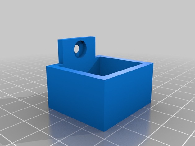
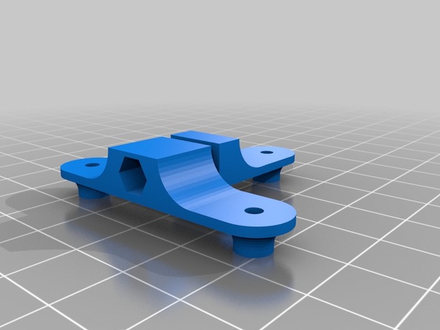
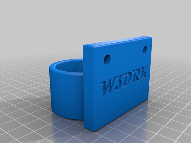
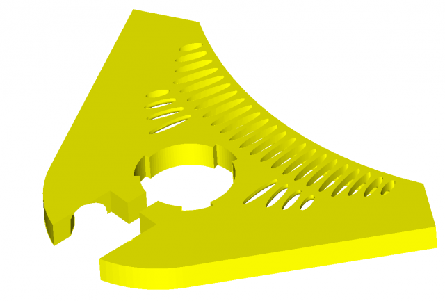
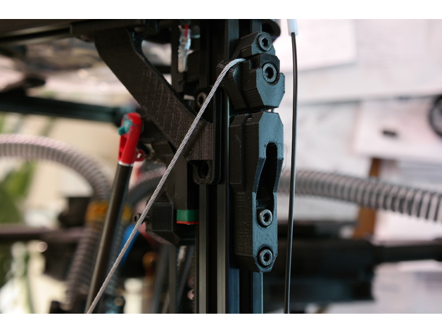
Terminology notes: the fixed anchors are the ones with TWO holes for M4x12s, while the adjustable anchors have ONE hole for an M4x12, and the screw adjust mounts are the guys with the big slot for the M5x20’s. The M5x20 bolts are the ones you’ll use for applying final tension later.
Assembly Steps:
Stick all 9 M5 nuts in all the sockets that need them.
Stuff an M5x20 into each of the screw adjust mounts’ slots and wind it all the way up, then back it off until the one of the adjustable anchors can fit on top of it with no space in the joint. See the pictures if you’re not clear on this.
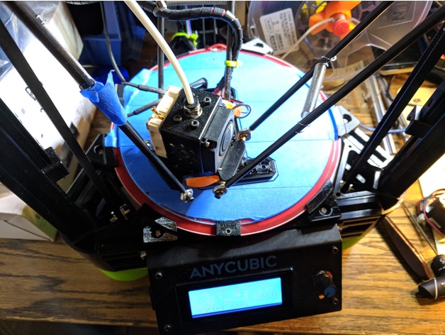
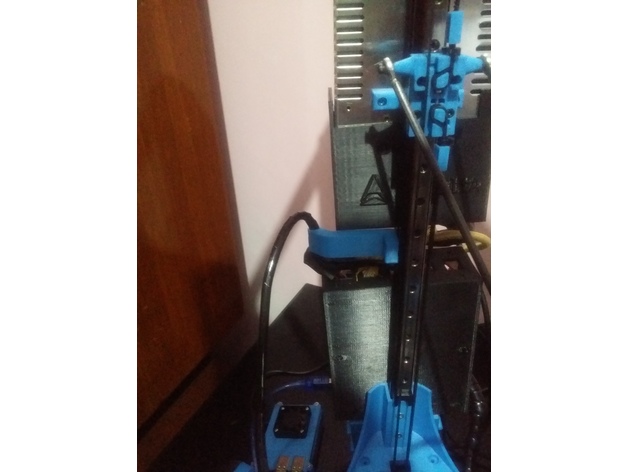
Bolt the 3 fixed anchors with the wire slot DOWN to the Kossel’s three uprights. Mount these as far down as they’ll go. (NOTE: you could slide them up a little bit — or a lot bit — to gain back some of your build envelope, but the higher they are, the more strain they’ll probably put on your plastic corner pieces. The goal is to have the twisting/tilting loads transferred as directly as possible into compression forces on the frame horizontals, and the further up the anchors sit, the more of a moment you’re inflicting on the corners to transfer the force).
Mount the 3 adjustable anchors at the top of each frame upright with the wire slots UP, and place them about 15-20mm down from the bottom of the plastic frame corner. You’ll need the extra travel above these for the final tensioning later. Don’t tighten these on too much.
Mount the 3 screw adjust mounts at the top of each frame upright with the M5x20 bolts inserted into the holes in the bottom of the adjustable anchors and scoot them all the way up so their top sides butt against the anchors’ bottoms (again, see the pictures…), then tighten them down. Make sure the M5x20’s are snug against the adjustable anchors, but not actually pushing them up yet.
The fun part: string the wire! Well, first put one end of the wire in the eye join and fix it good with two of the wire clips (leave yourself a tail of at least 5-8 cm); then wind the wire twice around the machine through the wire slots in each anchor, alternating up and down, until you get back to the eye join.
Run the second end of the wire through the eye join, snug it up, and tighten on two wire clips just enough to hold the wire in place. Clip off the excess wire, again leaving yourself a tail of at least 5-8 cm.
Now it’s the really fun part: applying the tension!
FIRST, give the top of your frame a rock and a twist to see how much it can flex, just so you have a point of reference when you rigid it up.
NOTE that this design uses a single loop of wire strung all the way around the machine so that you can avoid all the hassle of trying to get six different pieces of wire the exact same length and tension — as long as you don’t lock down the clamp washers until the very end, and make your tension adjustments in small increments to each joint in turn, you should get perfectly even tension all the way around. You can test for even tensioning as you go by simply plucking the wires — if they all generate the same tone, you know you’re good.
We kick off this process by getting as much slack out of the wire as possible by hand, without using the screw adjusters. Do this first by just going around the machine, snugging up each length of wire, and working the slack around to the side with the eye join, then tugging the slack through the eye join and wire clips to hold it in place. IMPORTANT: make sure you get the eye join someplace where you’ll have enough room for both tails, but also where it won’t risk interfering with the printer’s arms. I chose to mount mine pretty close to the top of its side, since the arms can only bump the wires on the bottom halves. This is very much most convenient to get situated while you’ve still got slack.
Once you’ve got most of the slack out, you can go ahead and mount all the clamp washers with the M5x12s. DON’T tighten these on, just get them on enough to put a tiny bit of friction on the wire.
Okay, now you can GENTLY tighten ONE of the clamps for the side with the eye join. This will hold that corner in place so we can work out slack around the machine and back to the eye join to take it out.
Start working around the machine again, taking out slack (easiest way to do this is to pull the wires gently OUT or IN, one segment at a time, in order) from the fixed corner and back to the other side of the eye join, where you can work it out through the eye and wire clips.
Don’t go crazy with the wire, just get it so it’s not sloppy. Now is a good time to do an initial check of how your build envelope is going to change by checking where the arms will touch the wires around the outside of the volume, and to make sure that your bowden and wiring have freedom of movement throughout the printable area. I ended up routing both through the bottom/center quarter of the same side of the printer, but had to shift my extruder a bit to get the bowden moving freely. Be especially sure that the wire and bowden can’t get caught with a loop on the wrong side of the wires in the case of a homing move starting close to that side of the build plate.
When you’ve got the slack pretty well out, tighten down all the wire clips really well on both sides of the eye join.
Now loosen that one clamp back up, along with the bolts holding on the adjustable anchors.
GENTLY screw in the M5x20’s in the screw adjust mounts until they all have about the same tension on them.
Now start going around the machine, CAREFULLY tightening each M5x20 bolt by 1/4 to 1/2 turn each time. The tension will rise faster than you think. GENTLY rock/twist the top of the machine from time to time — this will let you track how the rigidity is coming along, plus it will help distribute the tension evenly by helping the wires scoot around the corners if they need to.
When the frame feels decently solid and the wires feel decently and EVENLY taut (they should make a clear bass note when plucked, and all play about the same note), go ahead and re-tighten the M4’s on the adjustable anchors to fix them firmly to the frame.
This is also a good time to go around and make sure all the other M4’s are good and tight, and to re-tighten the bolts on the frame corner braces that you loosened earlier.
FINALLY! Go around the anchors in order and gently tighten each of the M5x12s to tighten up the clamps. This will put a final lick of tension on the assembly.
Okay, last steps:
You’ll want something on the wires to prevent wear and tear in the event that printer parts do contact the wires. I used scissors at an angle to spiral-cut some plastic drinking straws, which made pretty good ad hoc fenders when wound onto the wires and taped together at the crossing. The bottom halves are crucial to shield against arm contact, along with anywhere your bowden, wiring, etc. might brush up against.
Test carefully at first! A gentle bump or slide of the arms against the wires won’t hurt (the wires will give outward a bit even under a lot of tension), but a hard crash into them could seriously strain your frame. Likewise pay close attention to your bowden and wires until you’re confident they’re not going to bind anywhere. I assume no liability if you bork up your machine with this.
Re-level your printer after this mod (duh).
There’s going to be a wear-in period where some tension is lost to the wires conforming better to the corner radii, the PLA deforming a bit, etc. After a few prints, start by re-tightening all the M4’s holding the anchors to the frame, then loosen all six corner clamps again, along with the adjustable anchors’ M4s, and go around in order again, tightening the M5x20’s by a quarter turn at a time, until you’re back where you want to be, then tighten the adjustable anchors’ M4s again, followed by all the clamps. This might need to happen a few times.
Probably also get some loctite on the wire clips’ nuts.
How I Designed This
I genuinely don’t know why nobody’s thought of this one yet (or if they have, I couldn’t find jack about it on Google).
The problem: if you’ve got a Kossel, you know it’s not a rigid setup. You’ve got plastic corners (or possibly metal) to keep the uprights true, but they don’t have much leverage, whereas the forces inflicted on the uprights are pushing way up high, where they have tons of leverage. Take the top frame and push it or twist it and watch what happens to your effector head — it’s going to shift all over the place. It’s not a good recipe if you want to go fast, because going fast takes high acceleration rates, which means you’re pushing your frame harder, which means every start, stop, and corner is like hitting your frame with a bat.
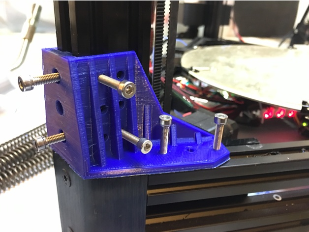
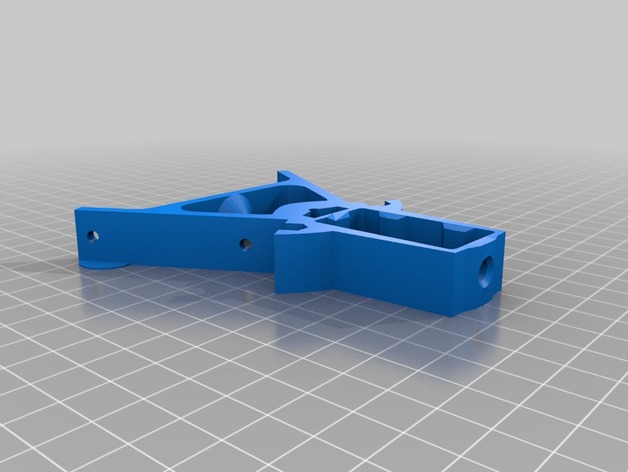
I figured this out pretty quick when I got my Kossel, and my first fix was designing some bolt-on corner reinforcements. They definitely helped with the ringing that came from the stock frame’s lack of rigidity, but they only reduced it, and the reason is pretty obvious from an engineering perspective: they just don’t have good mechanical advantage compared to the forces they’re meant to counteract. I got especially worried about this when I took out my steppers to put in some dampers and discovered that two of the three corners had cracked across the motors’ mounting faces. No idea when that happened, but heaven knows I’d been pushing my printer hard.
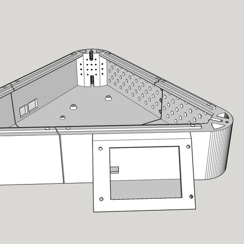
Anyway, from the inadequate corner braces, the next logical step is to look at stiffening up each side of the frame with longer braces, and the best-case for this would be braces that go all the way from corner to corner. Rigid braces would be ideal, but difficult in practice — you’ve got to get the lengths and mounting angles perfect to avoid wracking the frame out of true, plus at those lengths you’re not going to be able to count on good resistance to compression forces without having pretty fat chunks of CF tubing or similar, which is going to cost. The other idea (as done on printers like the Fisher) is to mount nice, stiff plates either around the corners or across the sides; I’d regard this as probably the ideal solution, but not the easiest one to implement at home without access to equipment for doing a really precise job of cutting the plates (and/or bending them) and getting all the holes in exactly the right spots. Plus, again, the plates will probably need to be made of something not-cheap even if you don’t have to pay somebody else for the custom fabrication.
So I wondered: why not just go for purely tensile bracing, which would mean nothing more complicated than steel wires? They’d self-align, and if I used a single loop they’d also self-adjust for even tensioning around the structure. Plus, with all the anchors mounted to the uprights, I figured the wires ought to be able to take on a lot of tension without putting terrible strain on the corners. The main tradeoff, then, would be balancing how far to mount the wires from center on the uprights, because too far out would mean giving the anchors a big moment arm to translate the uprights’ deviations from vertical into twisting forces on the uprights themselves (bad for the corners), but too far in would start cutting into the usable print volume by limiting how far side-to-side the printing arms could move. My first design iteration errs well to the “closer to the center” side of this, but if I really start to miss my lost printing volume, I’ll probably start experimenting with how far I can spread the wires without endangering the plastic corners.
Initial testing has shown that these wire braces can improve frame rigidity a LOT for a minor build volume loss; time will tell how it translates into more (or less, hopefully) wear and tear on the rest of the printer from reduced cyclical wear on the frame.
Oh yeah, and that secret to warp speed? Go into your firmware and change your DEFAULT_MAX_FEEDRATE to something like {400, 400, 400, 400} and your DEFAULT_MAX_ACCELERATION to something like {9000,9000,9000,9000}. If you’ve never done this, you’ve probably been stuck all this time with a speed limit of 200mm/s and 3k mm/s^2 on all axes. Even if you don’t push your speeds/accelerations up to these new limits, you might be surprised at the effect of raising them — in my case, I think my extruder had been constrained somehow by the lower limits, because until I made these changes my prints always suffered from underextrusion above about 30mm/s at 0.2 layer height.
But once you’ve raised the limits, it’s worth seeing what a 350mm/s travel move really looks like at 5500 or 6000 mm/s^2. (Answer: sorta scary, honestly)
Designed from scratch in SketchUp.