Summary
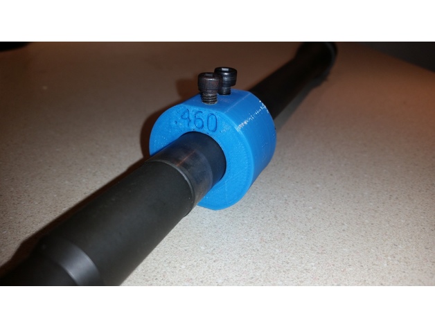
Barrel Dimple Jig for .75″ gas block with .620″ hole spacing. Drill the 4 holes to 5/32″ and tap 2 top holes with a 10-32 tap. Use a cone set screw to line up and gas hole and drill the other side to dimple your barrel.
Print Settings
Printer Brand:
Robo 3D
Printer:
R1 ABS + PLA Model
Rafts:
No
Supports:
Doesn’t Matter
Resolution:
.2
Infill:
30%
Tag: jig
-
Barrel Dimple Jig 3D Print Model
-
Prusa Multimaterial upgrade heatsink PTFE cutting jig – 41mm 3D Print Model
Summary
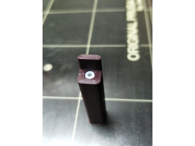
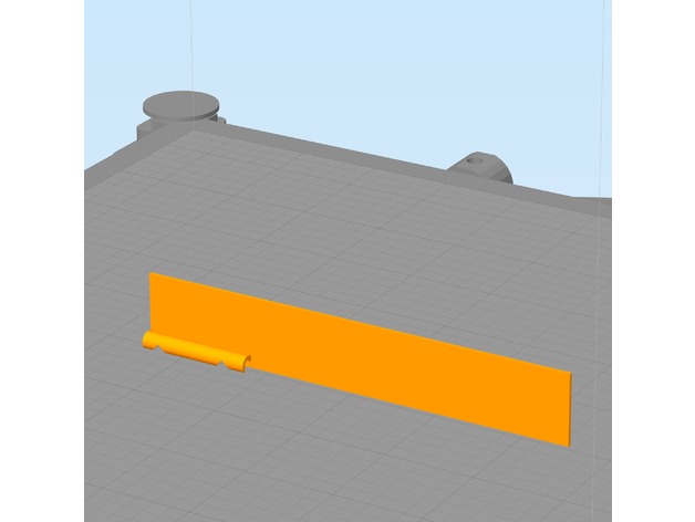
A very simple jig to enable precisely 41mm of 4mm OD PTFE tubing to be cut to insert into the top of the MMU heatsink. Insert tubing all the way into the hole and cut parallel and flush with the wall at the entrance point.
Please note that this is not the only step required with this tubing. It must also be reamed and chamfered (official specs here). Also note that the inside diameter of this tubing is specified as 1.85-1.9mm, which is not the same as you will find on generic PTFE tubing.
Print Settings
Printer:
Original Prusa I3 MK2 MMU Rafts:
Yes Supports:
No Resolution:
0.2mm Infill:
Doesn’t matter Notes:
Use a small brim and print vertically. I printed this with 4 perimeters. Insert tubing all the way to the end of the jig and wse a razor or utility knife blade and cut flush with vertical surface at entry point. -
Squid Jig size 3.0 3D Print Model
Summary
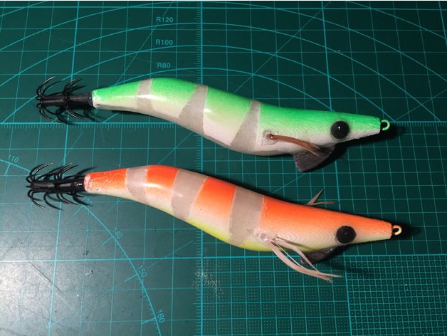
This is my design for a size 3.0 squid jig.
Print Settings
Printer Brand:
RepRap Printer:
RepRap Kossel Rafts:
No Supports:
Yes Resolution:
0.2mm Infill:
10% Notes:
Use glow in the dark PLA for better performance at night.
Post-PrintingThe first thing to do is to print the parts, and get the other hardware together.
You will need:
Wire for the nose ring (I used stainless lock wire)
Lead for the keel weight. You can use a sinker, or any lead really, bash it into shape. This needs to weigh around 4 grams.
Barb crown for the tail. You can either cut up a small pencil jig, or get a new set of barbs.
The best I’ve found are Harimitsu brand, you can get these here: http://www.fishonproshop.com.au/fishonproshop/SelectProd.do?prodId=657The parts go together like this.
Glue the two halves together, with the nose ring and lead keel in place. Leave the barbs out for now, you can put them in later.
Have fun with masking out the lure and painting it. Ensure that you sand the layer lines off before painting.
Glue the eyes in after painting. I print the eyes in black filament, so that there is less to paint. You can use whatever colour you like, obviously.
After painting, you can cover the lure in a layer of clear epoxy. Keeping the lure rotating for a couple of hours can keep the coat more even, and eliminate drips. This is a simple setup to keep the lure rotating while the glue cures.
Finally, glue in some feathers and the barb at the back, and you’re ready to catch some squid! -
Snap-on CTC Dual bed levelling jig 3D Print Model
Summary
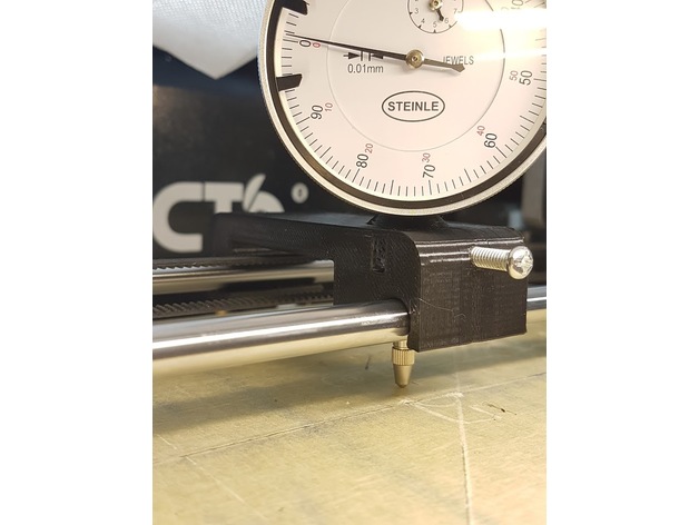
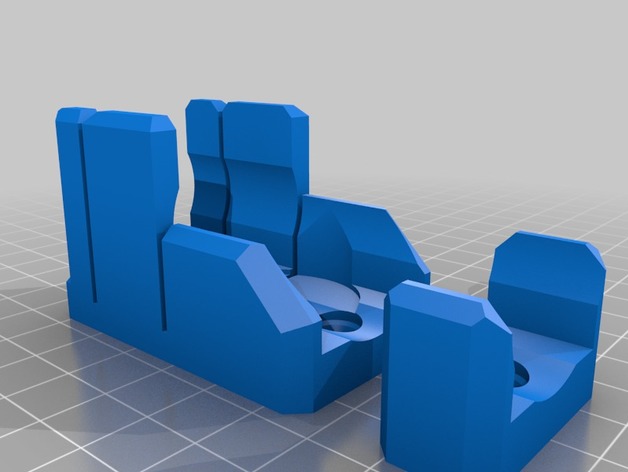
Designed from scratch using the layout and coarse dimensions from https://www.thingiverse.com/thing:2460482
OnShape link where you can edit to your custom specifications: https://cad.onshape.com/documents/28e0bcaa853c187d0624b81f/w/fd7acef5713bafce038c5cfe/e/7e7969d14473af0ccc5dd0ed
Improvements:
snaps on instead of using magnets or other means
wider base for improved stability
longer support for the indicator shaft
offset on top to allow clearance for the indicator dial
Instructions: printed laying on one side, PLA, infill 15%, no raft or support. The indicator shaft will deform a bit while printing, hence why it’s oversized.
Design notes:
Distance between rails is 70mm, rail diameter is 8mm, indicator shaft diameter is also 8mm. All holes have been oversized to 8.5-8.7mm, this is both to allow for printer tolerances and to make it easier to slide the “carriage”. You can edit the first two sketches to reduce the oversize, if you want a tighter setup.
I currently have about 0.05mm slop/play with this setup, but my bed is warped almost 0.2mm, so the jig play doesn’t affect the readings so much.
The chamfer on top is ugly but allows for better printing without supports.
The snap-on distance is 0.7mm. You can increase it if you want a tighter fit, decrease it if the required force to snap is too high.
Post-printing:
The indicator should be a tight fit (“good enough”) but there is a hole for an M4 screw that’s designed to be tapped. There’s also an M4 nut retainer, if you don’t want to tap the hole. You can also probably just drive the screw in, without tapping, -
E-Step Calibration Jig (3mm filament) 3D Print Model
Summary
Trying to hold calipers or a ruler next to my filament while marking it for E-Step Calibration isn’t always easy, especially if your printer is in an enclosure. This jig has 2 notches. The lower notch is at 100mm the upper notch is at 120mm. Snap the filament channel onto the filament and lower the jig until it touches the top of the extruder. Then use a fine point marker to mark inside the V slots as shown in the photo. This jig requires your printer to be reasonably dialed in. You can use calipers to inspect the printed part for accuracy. I have found this tool to be quite handy.
E-Step calibration guides can be found in many places, I follow this: http://reprap.org/wiki/Triffid_Hunter%27s_Calibration_Guide#Measure
This is designed to be printed with the filament channel facing downward and a wide brim. The model was also designed to print with a .5mm nozzle but should print fine with smaller nozzles. The brim secures it to the build platform. Remove the brim after printing. See photos for usage.
Print Settings
Printer Brand:
LulzBot Printer:
TAZ 6 Rafts:
No Supports:
No Resolution:
.2 mm Infill:
none Notes:
This is designed to be printed with the filament channel facing downward and a wide brim. The model was also designed to print with a .5mm nozzle but should print fine with smaller nozzles. The brim secures it to the build platform. Remove the brim after printing. See photos for usage. -
Tak Piece Cutting Jig 3D Print Model
Summary
This jig is made to use with 1″ square and/or 1-1/8″ round dowel. There is an end stop for a 10mm slice (~3/8″ after sanding), and a spot to place the discs to trip a flat. The second holder is to support the length at a greater distance. There are screw holes for #6 or #8 drywall screws. that can be used to screw it down to a 1×2 or other support.
I have a portable work bench with clamping sections. I made the bottom plates to work with M3 bolts to clamp down on a slot of my workbench which secures it entirely satisfactorily. #6 bolts would likely work just as well. The holes may need to be expanded a bit, but should be tappable.
I printed the jig and support with 3 walls and 15% infill, the clamp plates with 4 walls and 35% infill. -
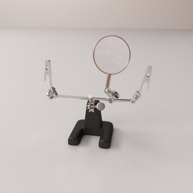
Helping Hand 3D Model
HELPING HAND=================================- Modeled in Blender.- Preview image rendered using cycles.- All scene are included in .blend files.- Poly count are before sub division- Great for close up render.- All parts and materials are logically named.OTHER FORMATS=================- 3ds MAX- COLLADA (.dae)- Autodesk FBX- OBJ