Summary
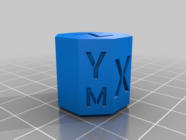
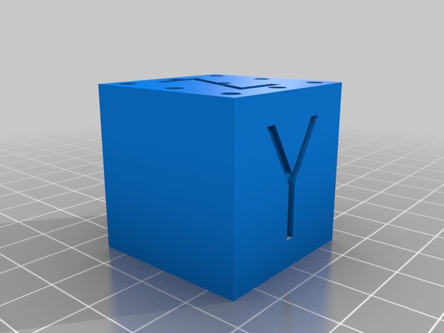
Now you can check if your belts lengths are correctly tuned and check the quality of the single motor movements!
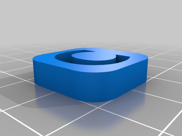
The parallel faces are all 20mm apart and there is a small chamfer at the base to cut any problems with elephant foot.
I’ll tune the font ASAP. Not printed yet,
Print Settings
Printer:
Hypercube Evolution
Rafts:
No
Supports:
No
Resolution:
0.2
Notes:
Do not worry about the thin parts of the letters of the motor faces. 😀 I just like the font and would like to test it.
Tag: Calibration
-
CoreXY Calibration Ocatagon (“cube”) 3D Print Model
-
texture cube calibration test 3D Print Model
Summary
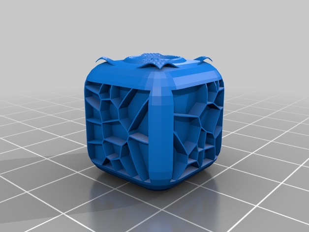
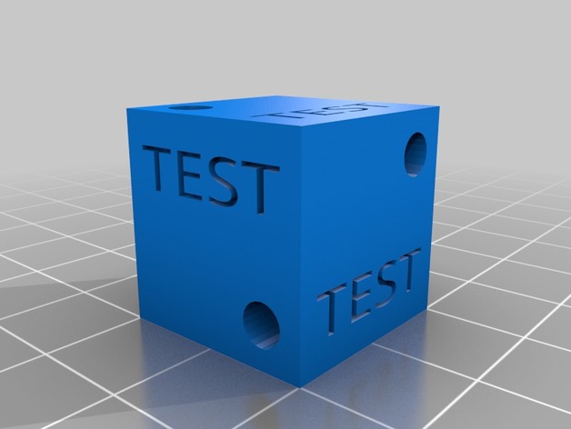
test calibration of your printer with the texture cube. plus it’s fun to feel. -
30mm Calibration cube for SLA printers – Hollow 3D Print Model
Summary
This is a hollow cube with drain holes to minimise suction. Stick it on some supports, print it and measure
When I used this on my Moai with v1.15 firmware, using “m” as the relevant cube measurement, the formula to calculate what put in the relevant X or Y entry is:
900*(30/m)
I haven’t used it on my D7 yest, but I’m sure you can work out what formula you would need to use. -
Calibration Wall 9×3 mm 3D Print Model
Summary
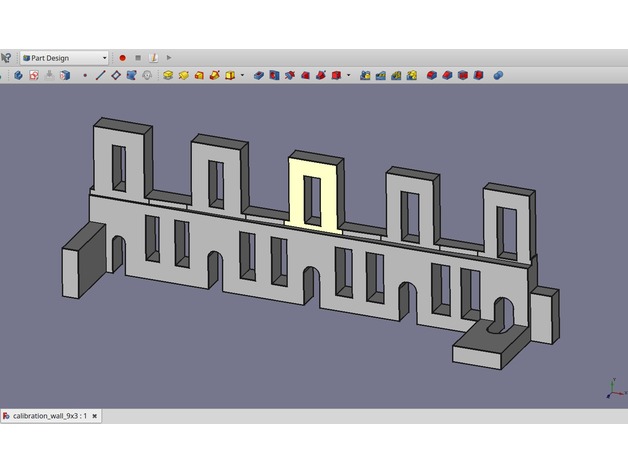
This part has tabs and holes.
The center tab of the row of 5 is supposed to be exactly 9×3 mm in size. Same for the hole in this tab. The two tabs to the left and to the right are smaller and bigger with increments of 0.2mm. The holes to the left and to the right have increments of 0.1mm.
There are three extra tabs down on the build plate, all of them exactly 9×3 but in different orientations.
If you print two, try one of the 9x3mm tabs to fit in the holes. You will see if your printer generates holes too small or too big. If so, chances are that walls are also too thin or too fat.
In Cura the parameter to compensate for this is called ‘horizontal expansion’. A negative value is needed, if holes are too small.
This test assumes that scaling is already correct. E.g. a 100mm rod is 100mm long. Plus minus a few tenths of a mm.
If you only print one, you can easily break away one of the three outer tabs, or cut away one end. -
Calibration Testcube with bores 3D Print Model
Summary
simpe testcube for x y z axis bore calibration -
E-Step Calibration Jig (3mm filament) 3D Print Model
Summary
Trying to hold calipers or a ruler next to my filament while marking it for E-Step Calibration isn’t always easy, especially if your printer is in an enclosure. This jig has 2 notches. The lower notch is at 100mm the upper notch is at 120mm. Snap the filament channel onto the filament and lower the jig until it touches the top of the extruder. Then use a fine point marker to mark inside the V slots as shown in the photo. This jig requires your printer to be reasonably dialed in. You can use calipers to inspect the printed part for accuracy. I have found this tool to be quite handy.
E-Step calibration guides can be found in many places, I follow this: http://reprap.org/wiki/Triffid_Hunter%27s_Calibration_Guide#Measure
This is designed to be printed with the filament channel facing downward and a wide brim. The model was also designed to print with a .5mm nozzle but should print fine with smaller nozzles. The brim secures it to the build platform. Remove the brim after printing. See photos for usage.
Print Settings
Printer Brand:
LulzBot Printer:
TAZ 6 Rafts:
No Supports:
No Resolution:
.2 mm Infill:
none Notes:
This is designed to be printed with the filament channel facing downward and a wide brim. The model was also designed to print with a .5mm nozzle but should print fine with smaller nozzles. The brim secures it to the build platform. Remove the brim after printing. See photos for usage. -
Extruder Filament Feed Calibration Ruler 3D Print Model
Summary
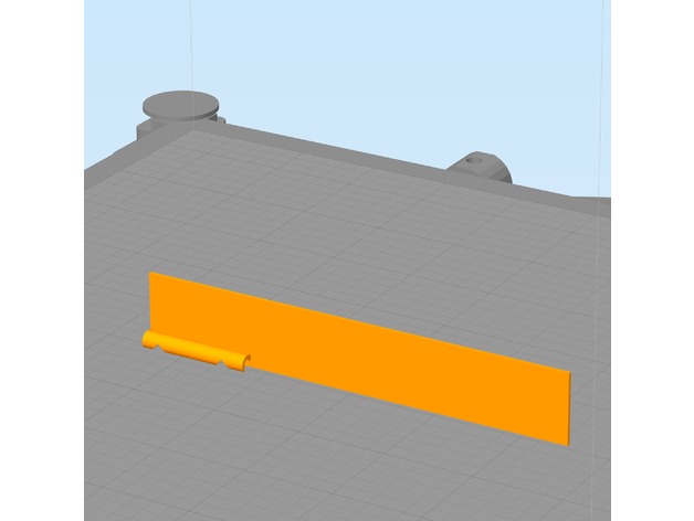
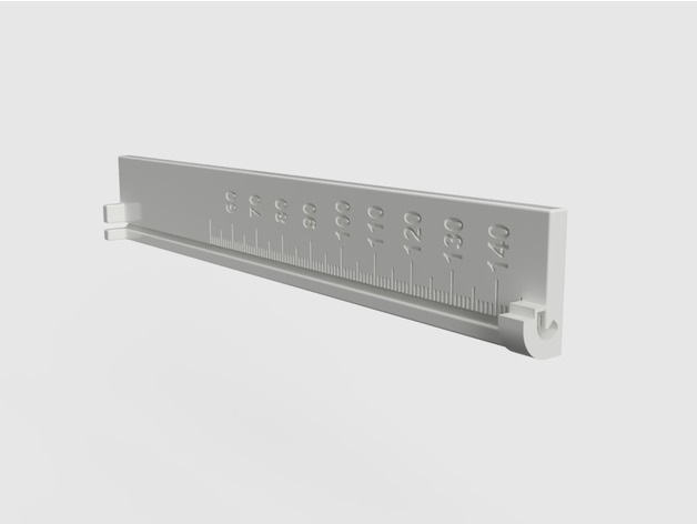
A ruler designed to mark the filament at 15 cm before feeding and reading off the actual length fed afterwards.
The filament snaps into the bottom and top of the ruler and fits into the grove to make reading off the length easier.
The length of the ruler is 15 cm with a ledge at the top that can be used as a guide for a sharp razor mark or marker line.
The markings on the ruler are in mm of actual fed filament to be read off where the mark lines up after feeding 10 cm of filament through the extruder.
Print Settings
Printer:
TEVO Little Monster Rafts:
Doesn’t Matter Supports:
No Resolution:
0.2 mm layer height Infill:
30%, not critical Notes:
I printed mine with ABS but see no reason why this would not work in PLA.
Print settings
0.2 mm layer height
30% infill, not critical
no support, already included in the model
raft does not matter
Post-Printing
You need to clip off the tiny support holding the end of the clamp at the bottom of the ruler.
How I Designed This
After realizing that the extruder feed accuracy needs to be tested for new filaments I decided to make a ruler designed for the task that allows easy marking and measuring of the extruder filament feed length and does not require three hands to hold the filament in place.
I am new to 3D printing and find Fusion 360 to be the easiest to use when taking an idea to a working model.
I use parameterized dimensions to allow easy tweaking and reducing the model size for faster test prints.Custom Section
Marking 15 cm before filament feed
Snap the filament into the top and bottom clamps of the ruler and press into the grove along the scale.
With the bottom of the ruler resting on the extruder intake mark off 15 cm using the top of the ruler as a guide. Only the bottom of the mark is relevant so don’t worry about how thin it is.
Reading actual feed length
After feeding 10 cm of the filament with:
G92 E0; reset extruder origin
G1 E100 F120; feed 10 cm of filament at 120 mm/min (adjust this to your usual feed rate
G92 E0; reset extruder origin
Read off the actual length from the bottom of the mark aligning with scale printed on the ruler. Numbers are in mm of actual feed. In the image, I adjusted my extruder steps/mm to compensate for always underfeeding by 5mm on 100mm feed so it is showing 100mm. -
Dual extruder calibration stl 3D Print Model
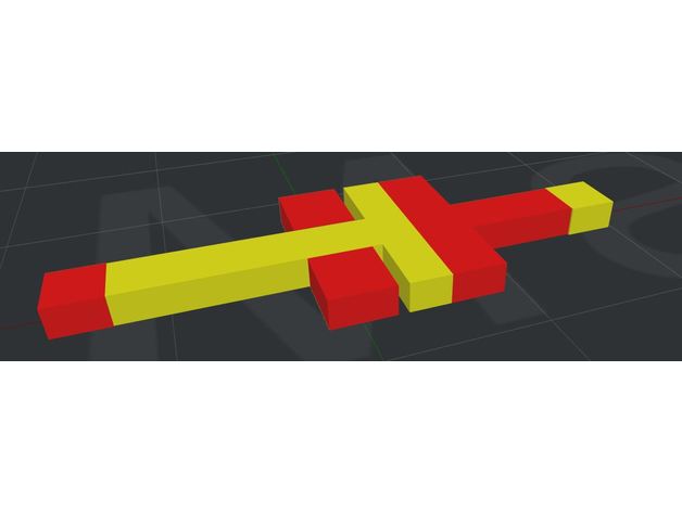
Summary
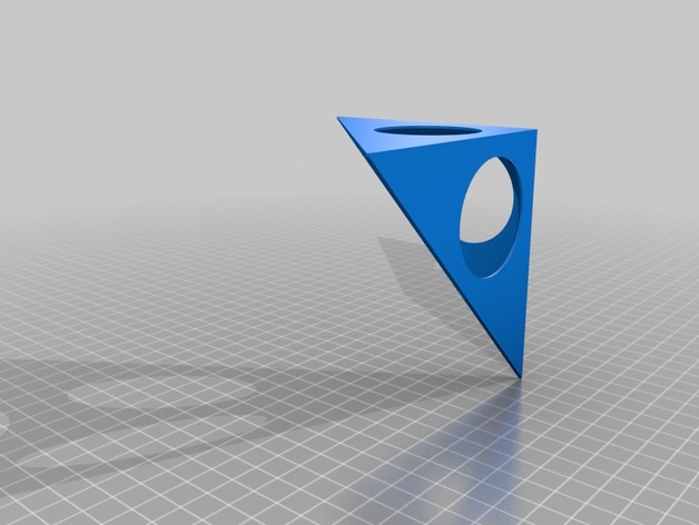
Helpfull to choose offset X and Y in the printer setting for double extruder printing.
I use it for raise3d N2 Dual +
After 6 printing – i moved offset X & Y step by step. The calibration was good for bigger printing.
Print Settings
Printer:
Raise3D N2 dual plus Rafts:
Yes Supports:
No Resolution:
0.15 Infill:
30% rectilinear
Post-PrintingHow I Designed This
Tinkercad.com
Dual calibration .stl made with tinkercad.com -
Calibration Steps 3D Print Model
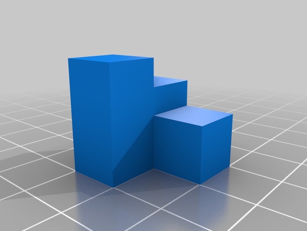
Summary
A simple calibration test made in Solid works.
Long sides are 20mm, short sides are 10mm and the middle square height is 15mm (just for fun). This way you have a few different lengths to test your printer calibration while using less filament then printing a 20mm cube.