Summary
This is holder for GU10 led bulb with diameter 110mm. This have ball type adjustment.
Tag: adjustment
-
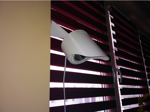
Lamp/holder for led bulb GU10 with adjustment 3D Print Model
-
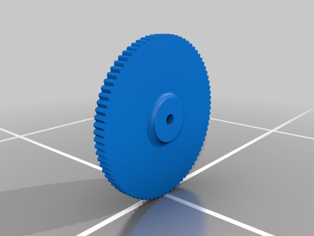
Adjustable 3d Printer Height Adjustment Wheel – M4 Nut 3D Print Model
Summary
Adjustable 3d Printer Height Adjustment Wheel for M4 Nut
How I Designed This
Used Inventor -
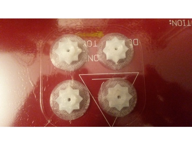
Geeetech i3 Hotbed adjustment nut 3D Print Model
Summary
First thing printed !! The wingnuts to adjust the hotbed are not very confortable to turn, it is a two hands job, so the first thing I printed are these knobs. As I had only some nylon to print with, I added a .5mm skirt to make the piece stick better to the bed as in the first try it got loose and went moving around. I printed without supports, and when the print was high enough, I paused and drop the M3 nuts in, so the top side would have something to lay on. -
Cylinder position mechanism 3D Model
Cylinder position mechanism, the mechanism design is clever, the design constraints to internal card slot, as long as cooperate with the pin shaft can be realized before and after the two position constraint, this can have in the assembly line or the fixture positioning clappers positioning function, simple is clever, save a space.This model is transformed into step and iges general model download, please refer to!Also includes 3d original files, welcome to download!if you like,you can paypal for you to get this models or if you have any questions also you can email to me.
-
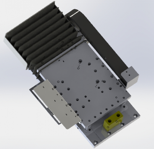
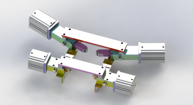
The gear and rack drives the manipulator 3D Model
The gear and rack drives the manipulator, and the model is different from the normal module. The gear rack and the slide rail module are used to cooperate with the motor driven by the motor to achieve the purpose of delivery.Advantages: low cost, save cost by not adopting screw mechanism, adopt gear mechanism, drive big, load high, fast, steady.This model is transformed into step and iges general model download, please refer to!Also includes 3d original files, welcome to download!if you like,you can paypal for you to get this models or if you have any questions also you can email to me.
-
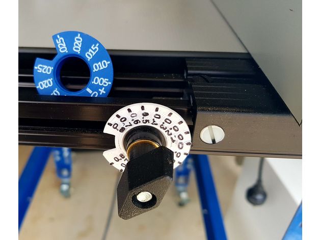
Kreg Router Table Metric Fine Adjustment Gauge 3D Print Model
Summary
While the Kreg Router Table can be supplied with metric units on the flat tapes, the fine adjustment dial is still in imperial. Here is my replacement for this.
It needs to be printed as two part, but they press fit together. A small amount of CA glue can be used.
3D printing in white is recommended so that the numbers can be easly highlighted with a black sharpie. -

Adjustable Wrench model 3D Model
-Modeled in 3ds Max 2016-Rendered using V-Ray 3.40.01Features:- The Object is correctly scaled and centered at the origin- Objects, Materials and Textures are properly named and logically grouped.- No N-GONS: Quads and Triangles only- Smooth function can be used to increase mesh resolution if necessary.- Max file contains geometry with Turbosmooth modifiers applied. – Units of measurement – centimeters.- Object dimensions: 26×7.5×1.6cm- Procedural texture and bitmap scratches 4000×4000 (normal, reflect) – All textures are included in archive- Ready to RENDER. HDRI map included (1500*750)- Clean UVs (Non-overlapping) File Formats:- 3ds Max 2016- 3ds Max 2013- FBX_2012- OBJ Number of polygonsSubdivision Level 0: Polys: 12 414Verts: 12 379Subdivision Level 1: Polys: 99 180Verts: 49 588Subdivision Level 2: Polys: 396 720Verts: 198 358
-
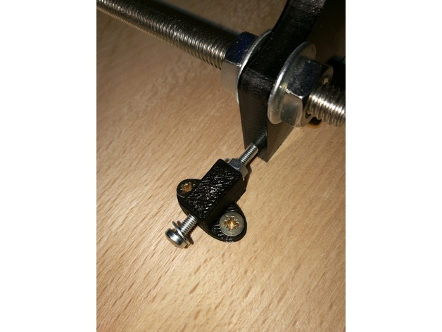
Anet A8 adjustment for Y-axis and printer leveling 3D Print Model
Summary
I’ve had the problem the floor on which the table for the printer stood wasn’t leveled. Which led to corners at the z-axis which haven’t had 90°. The same happened at the y-axis, because the threaded bars are bent.
If you just have a problem with a bend y-axis:Parts List:
Wooden board
10x screws for wood 3×12
1x M3x30
2x washer for M3
1x nut for M3
Angle profile length ~240mm
First cut the angle profile in two parts of ~62mm length and two parts of ~50mm length.
Drill in every part two holes and screw the ~62mm parts at the front of the housings and the ~50mm parts at the sides.
Print the STL, put the M3 screw with the washers and the nut in the small hole and screw it onto the wooden board near the side of the frontplate of the y-axis. Use the M3 screw to adjust the y-axis.
If you also have problems that your printer isn’t levelled perfect horizontally:
Parts List:
4x screwable case legs
Drill 4 holes in the corners of the wooden board by following the manual of the case legs. Use a water bubble to level the board.
Print Settings
Printer:
Anet A8 Rafts:
No Supports:
No Resolution:
0.2 Infill:
100% -
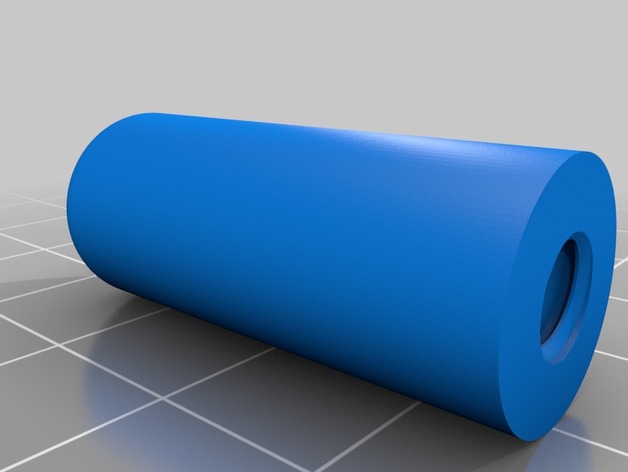
Cub Cadet Deck Height Adjustment Button
Summary
Designed for my Cub Cadet HDS 2155 on which the deck height button had long been broken. Its a simple cylinder with a chamfer(.125″ if I remember correctly) on the top and 1/4-20 threads .75″ deep. This was modeled in Fusion 360.
Print Settings
Printer Brand:
Prusa Printer:
Prusa Clone Rafts:
No Supports:
No Resolution:
.12 Infill:
100% -
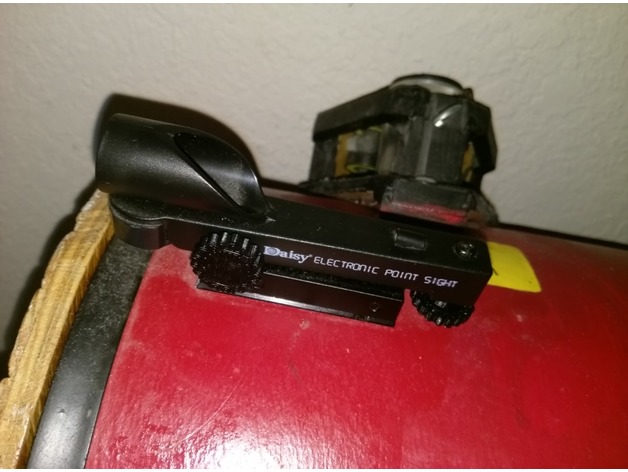
Daisy red dot sight adjustment knobs
Summary
This is an adjustment knob for a Daisy red dot sight, which makes it easier to dial in the azimuth and altitude adjustments. This is particularly useful if you use the sight on a telescope.
To use this, print two. Then make sure the hex nuts on the two Daisy adjustment screws are well glued onto their screws, because the knobs will attach to the hex nuts. If they aren’t well glued, then glue them to the screw with superglue. Then glue on the knobs (or just press-fit). If they don’t fit, increase the tolerance setting.
No supports needed.